Automobile seat

a technology for automobiles and seats, applied in vehicle components, pedestrian/occupant safety arrangements, vehicle arrangements, etc., can solve problems such as user discomfort, seat occupant support, and whiplash injuries, and achieve the effect of reducing cervical vertebral strain

Inactive Publication Date: 2010-04-15
DELTA KOGYO CO LTD
View PDF4 Cites 13 Cited by
  • Summary
  • Abstract
  • Description
  • Claims
  • Application Information

AI Technical Summary

Benefits of technology

[0011]It is accordingly an objective of the present invention to provide an automobile seat capable of reducing, in the event of a rear-end-collision, the strain on the cervical vertebra by moving the headrest forward to support the seat occupant's head and subsequently continuously support it even after the rear-end-collision.
[0017]The swing axis may be loosely inserted in an elongated opening defined in the swinging motion restraint member. In the initial state in which no load is applied to the seat back, the elastic member applies a load to the swing axis in a first direction via the swinging motion restraint member, while when a load greater than the predetermined value is inputted to the seat back from before, the elastic member applies a load to the swing axis in a second direction different from the first direction via the swinging motion restraint member to thereby hold the headrest at the position after the movement.
[0021]According to the present invention, during a normal motion of the seat occupant, the seat back can elastically support an upper part of the seat occupant's body, and a mechanism for moving the headrest forward does not work substantially. Accordingly, when the seat occupant leaves the seat, the seat back returns to an initial position. On the other hand, if a load greater than a predetermined value is inputted from behind an automotive vehicle in the event of, for example, a rear-end-collision, a lumbar part of the seat occupant moves the pressure member rearward to thereby swing the sub-frame about the hinge and move the headrest forward. Accordingly, the seat occupant's head can be quickly supported by the headrest.
[0022]Even after the rear-end-collision, because the headrest is held at the position after the movement, the seat occupant's head is continuously supported, thus making it possible to reduce a strain on a cervical vertebra of the seat occupant.

Problems solved by technology

Accordingly, a load is applied to a user's neck, thus resulting in a whiplash injury.
In this case, however, the user's head is often brought into contact with the headrest even in a normal sitting condition, and even a slight movement of the head causes the head to interfere with the headrest, thus making the user uncomfortable.
In the case of the headrest mounting structure as disclosed in Document 1, however, the headrest and the seat back tend to return to initial positions thereof by a biasing force of the coil spring after the forward movement of the headrest and, hence, the support of the seat occupant's head becomes insufficient, thus giving rise to a problem that a strain on a cervical vertebra cannot be sufficiently reduced.

Method used


Image

  • Automobile seat
  • Automobile seat
  • Automobile seat

Examples


embodiment 1

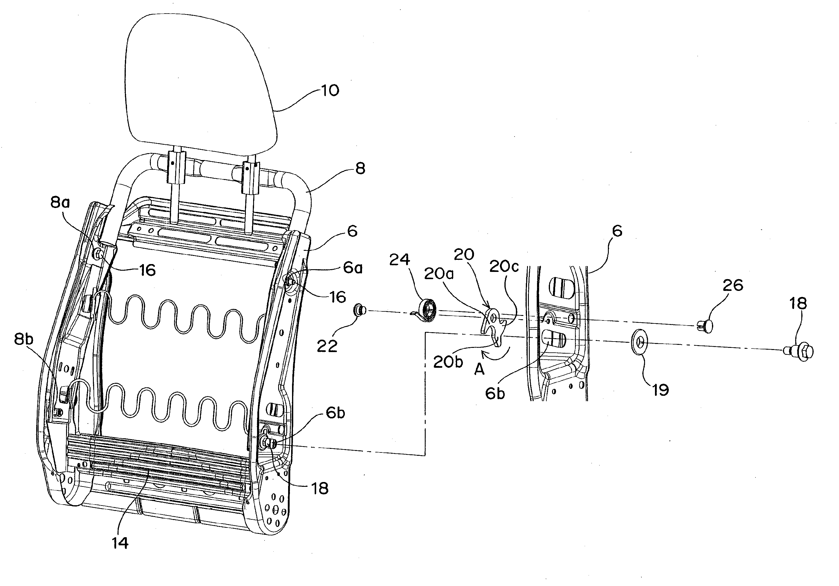
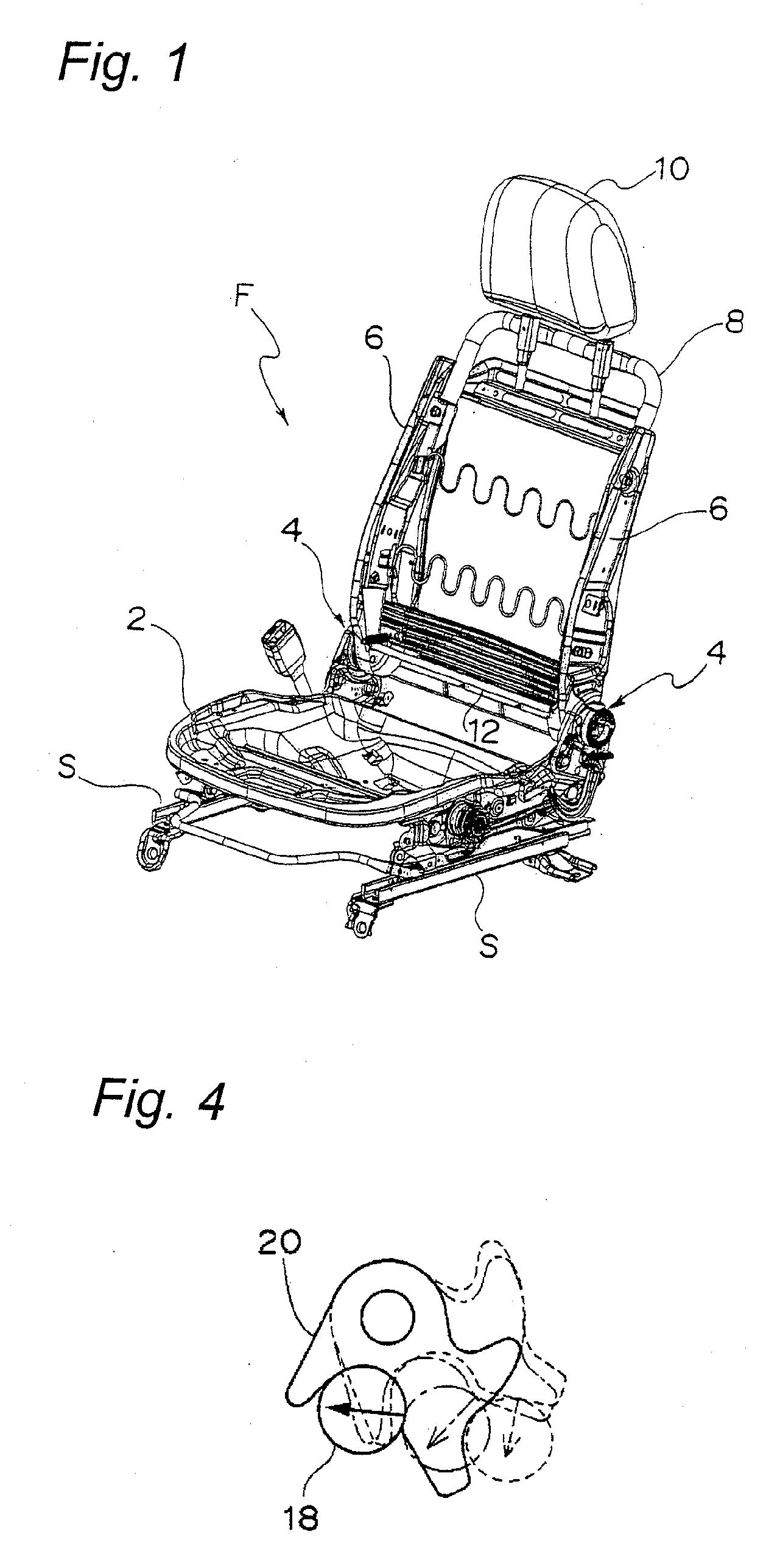
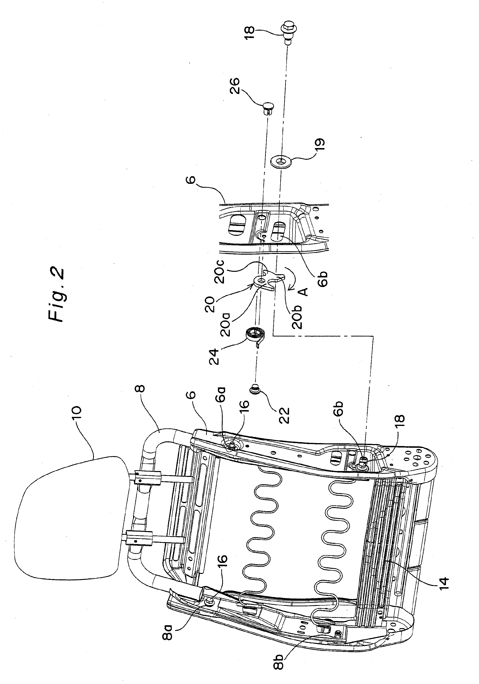
[0044]FIG. 2 depicts a seat back frame of an automobile seat according to a first embodiment of the present invention. As shown in FIG. 2, each side frame 6 has a hinge insertion hole 6a defined in an upper portion thereof and an elongated opening 6b defined in a lower portion thereof in which a swing bolt (described later) is loosely inserted. The elongated opening 6b is formed into an arcuate shape having a center of curvature at the hinge insertion hole 6a.

[0045]On the other hand, the sub-frame 8 is bent in the form of an inverted U and, hence, has a horizontally extending portion and two vertically extending side portions, each of which extends downward from one end of the horizontally extending portion. Each side portion of the sub-frame 8 has a hinge insertion hole 8a at a location confronting the hinge insertion hole 6a in the side frame 6 and a swing bolt insertion hole 8b at a location confronting the elongated opening 6b in the side frame 6. The sub-frame 8 also has a pre...

embodiment 2

[0068]FIGS. 9A and 9B schematically depict an essential portion of an automobile seat according to a second embodiment of the present invention wherein a swinging motion restraint member (swinging motion restraint plate) 20A and a coil spring (tension spring) 30 are used in place of the swinging motion restraint member 20 and the spiral spring 24 (or the coil spring 28) used in the first embodiment.

[0069]More specifically, one end (upper end) of the swinging motion restraint plate 20A is pivotally connected to the side frame 6 above the elongated opening 6b via a pin 32, and one end (lower end) of the coil spring 30 is secured to the other end (lower end) of the swinging motion restraint plate 20A. The other end (upper end) of the coil spring 30 is secured to the side frame 6 above the pin 32, thereby applying a clockwise or counterclockwise moment to the swinging motion restraint plate 20A. It is preferred that the other end of the coil spring 30 be positioned between the hinge bol...

embodiment 3

[0077]FIGS. 10A, 10B and 10C schematically depict a side frame of an automobile seat according to a third embodiment of the present invention wherein an elastic force of a coil spring (tension spring) 34 directly acts on the swing bolt 18 without the provision of the swinging motion restraint member 20 or 20A.

[0078]FIG. 10A depicts an initial state before a user sits on the seat, and FIG. 10B depicts a normal sitting condition in which a load less than the predetermined value is applied to the seat back. FIG. 10C depicts an operating condition of the sub-frame 8 when a load greater than the predetermined value is inputted to the seat back from before in the event of, for example, a rear-end-collision.

[0079]More specifically, one end (lower end) of the coil spring 34 is secured to the swing bolt 18, and the other end (upper end) of the coil spring 34 is secured to the side-frame 6 above the hinge bolt 16. A downward extension of a line that links the hinge bolt 16 and a position wher...


PUM


Abstract

An automobile seat includes a swinging motion restraint mechanism for restraining a swinging motion of a sub-frame relative to side frames. The swinging motion restraint mechanism includes a swing axis mounted on the sub-frame, a swinging motion restraint member rotatably mounted on one of the side frames and having a first contact portion and a second contact portion, both of which are brought into contact with the swing axis one at a time, and an elastic member for biasing the swinging motion restraint member toward the swing axis. In an initial state in which no load is applied to a seat back, the first contact portion of the swinging motion restraint member is held in contact with the swing axis, while when a load greater than a predetermined value is inputted to the seat back from before, the sub-frame is caused to swing about a hinge to thereby move a headrest forward, and the second contact portion of the swinging motion restraint member is brought into contact with the swing axis, thereby holding the headrest at a position after the movement.

Description

BACKGROUND OF THE INVENTION[0001]1. Field of the Invention[0002]The present invention relates to an automobile seat capable of preventing a seat occupant from suffering a whiplash injury when an automotive vehicle has come into a rear-end-collision.[0003]2. Description of the Related Art[0004]Automobile seats generally have a headrest mounted on an upper portion of a seat back. When a user sits on a seat, a predetermined clearance is present between a user's head and the headrest, but when an automotive vehicle has come into a rear-end-collision, a user's body moves rearward, and the user's head moves further rearward. Accordingly, a load is applied to a user's neck, thus resulting in a whiplash injury.[0005]It is possible to reduce the clearance between the user's head and the headrest to minimize the injury. In this case, however, the user's head is often brought into contact with the headrest even in a normal sitting condition, and even a slight movement of the head causes the he...

Claims


Application Information

Patent Timeline
Patent Type & Authority Applications(United States)
IPC IPC(8): B60N2/427
CPCB60N2/4885B60N2/888
Inventor TARUSAWA, MAKOTOUMEZAKI, KIYONORIDOMOTO, YASUHITO
Owner DELTA KOGYO CO LTD
Why Eureka
Try Eureka