Fixing element and apparatus for accommodating a fixing element

a technology of fixing element and fixing element, which is applied in the direction of fastening means, couplings, manufacturing tools, etc., can solve the problems of inability to operate the snap-on mechanism, inconvenient use of the fixing element, and inadequate contact force, so as to achieve better tolerance compensation and greater travel

Inactive Publication Date: 2010-04-15
SIEMENS AG
View PDF9 Cites 2 Cited by
  • Summary
  • Abstract
  • Description
  • Claims
  • Application Information

AI Technical Summary

Benefits of technology

[0007]An object of the invention is to provide a fixing element which generates greater travel in the case of a rotary motion of the fixing element and thus a better tolerance compensation.

Problems solved by technology

Hooking a module over a profile rail by means of a snap-on hook is disadvantageous in that the snap-on hook, in order to guarantee its ability to snap on behind the rail, has to have a play between a detent and the profile rail.
If this play does not exist, the snap-on mechanism does not work.
This play nevertheless results in an inadequate contact force prevailing between the module and the profile rail in the case of a correctly dimensioned snap-on hook in the locked state, said contact force not being well-suited for use under industrial conditions.
A solution of the previously cited module which can be engaged in a profile rail in which a screw connection is used rather than the snap-on hook, is also disadvantageous since a number of complete turns are needed in order to tighten the screw and the assembler requires more time for the assembly.
This connecting element is disadvantageous in that a travel resulting from the rotary motion is not sufficient to generate a required contact pressure.

Method used


Image

  • Fixing element and apparatus for accommodating a fixing element
  • Fixing element and apparatus for accommodating a fixing element
  • Fixing element and apparatus for accommodating a fixing element

Examples


Embodiment Construction

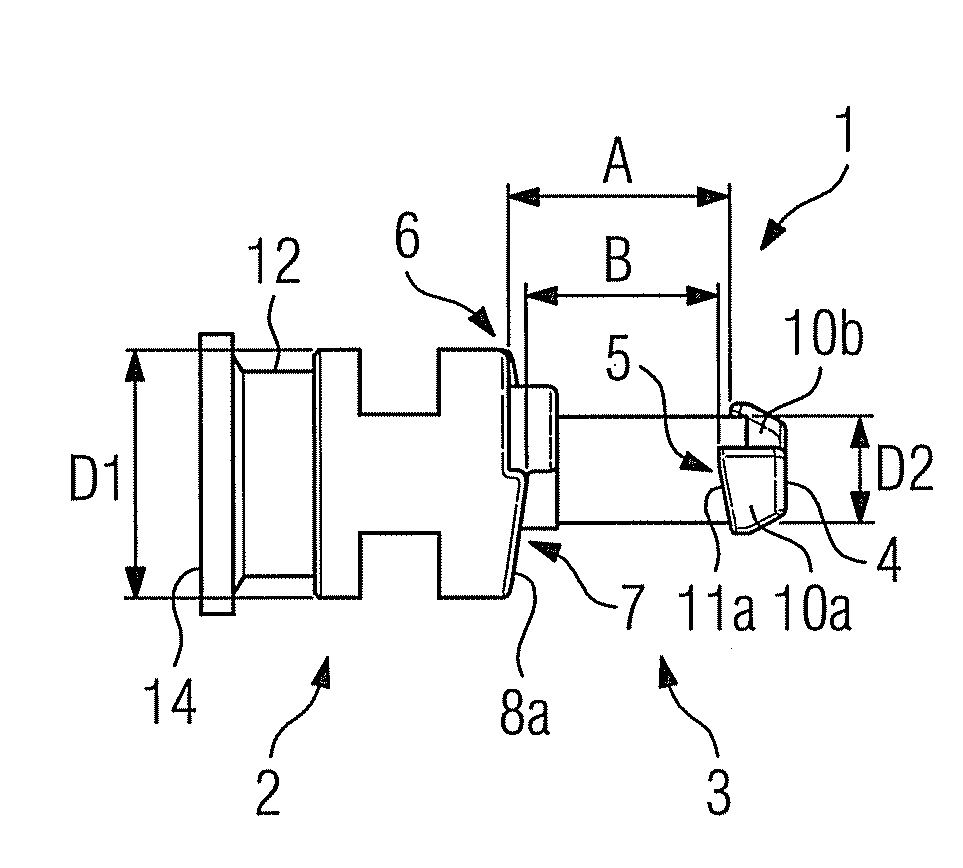
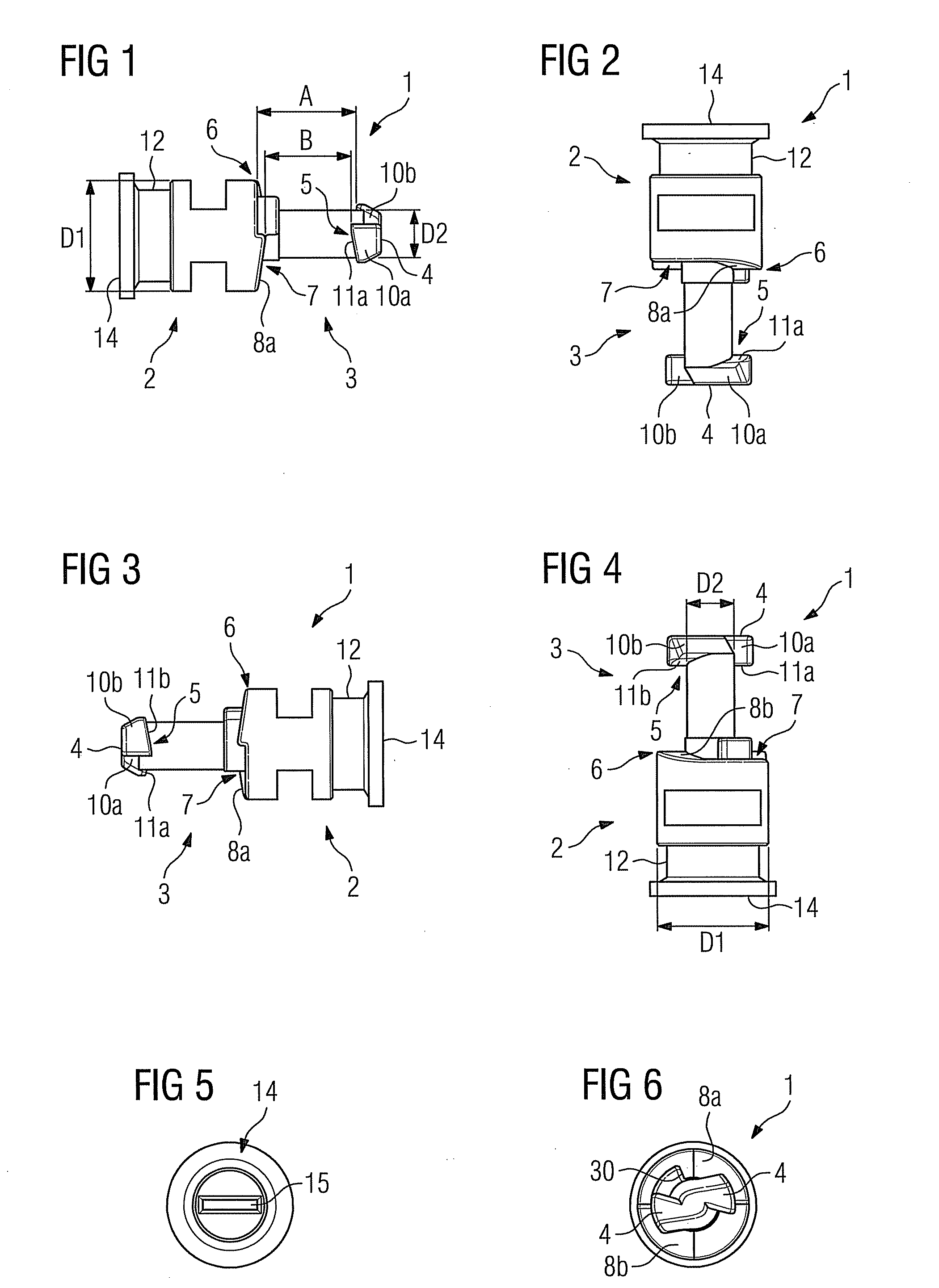
[0023]According to FIGS. 1 to 6, a fixing element 1 is shown in six views, with FIGS. 1 to 4 each reproducing a side view of the fixing element 1 which is rotated about 90° respectively and FIG. 5 showing a top view onto a head region 14 of the fixing element 1 and FIG. 6 showing a bottom view onto a clamping wing 4 of the fixing element 1. Based on FIG. 1, the fixing element 1 is formed by a bolt with a first region 2 comprising a first cross-section and a second region 3 comprising a second cross-section. The first region 2 essentially has a diameter of D1 here and the second region 3 essentially has a diameter of S2 here, with the diameter D1 being greater than the diameter D2. The diameter D2 jumps at a transition point 6 to the diameter D2 of the bolt. A second bearing surface 7 forms here on the transition point 6. The second bearing surface 7 has a first sliding part 8a and a second sliding part 8b, with, starting from an insertion position of the fixing element 1, a clamping...


PUM


Abstract

A fixing element including a bolt with a first region with a first cross-section and a second region with a second cross-section is provided. The fixing element further includes a clamping wing with a first bearing surface, the clamping wing being arranged in the second region, and a transition point between the first and the second region, which is configured at least partially as a second bearing surface. The first and the second bearing surfaces are arranged opposite one another such that a first material part and a second material part are mounted between the first bearing surface and the second bearing surface by executing a rotary motion. The second bearing surface includes a first sliding part and a second sliding part, wherein, starting from an insertion position, a tension force increasing in the axial direction until a locking position is reached as a result of the rotary motion.

Description

CROSS REFERENCE TO RELATED APPLICATIONS[0001]This application claims priority of European Patent Office Application No. 08017922.9 EP filed Oct. 13, 2008, which is incorporated by reference herein in its entirety.FIELD OF INVENTION[0002]The invention relates to a fixing element comprising a bolt with a first region having a first cross-section and a second region having a second cross-section, a clamping wing with a first bearing surface, with the clamping wing being arranged in the second region, a transition between the first and the second region, which is embodied at least partially as a second bearing surface, with the first and the second bearing surface being arranged opposite one another so that a first material part and a second material part can be mounted between the first bearing surface and the second bearing surface by executing a rotary motion.[0003]The invention also relates to an apparatus in a first material part for accommodating a fixing element including a cylin...

Claims


Application Information

Patent Timeline
Patent Type & Authority Applications(United States)
IPC IPC(8): F16B21/00
CPCY10T403/59F16B21/02
Inventor DEINHARDT, GUNTHERFURHOLZER, ROLANDRINGER, ULRICH
Owner SIEMENS AG
Why Eureka
Try Eureka