
Code division multiple access cellular communication system

ode technology, applied in the field of cdma cellular communication system, can solve the problems of large number of small underlay cells within a single macro-cell, extend the current approach to scenarios where neighbouring cells are not practical, and achieve the effect of facilitating the sharing of pilot signal scrambling codes, improving handover detection, and improving the operation of cellular communication systems

Active Publication Date: 2010-04-15
GOOGLE TECH HLDG LLC
View PDF14 Cites 49 Cited by
  • Summary
  • Abstract
  • Description
  • Claims
  • Application Information

AI Technical Summary

Benefits of technology

The invention is a cellular communication system that improves handover detection and reduces interference. It does this by using a unique scrambling code for each remote station and monitoring for signals using those codes. The system also allows for efficient resolution of handover targets and reduces the number of handover attempts. The invention also includes a method for determining the unique scrambling code for a remote station and a method for generating a potential handover detection. Overall, the invention enhances the performance and reliability of cellular communication systems.

Problems solved by technology

A widespread introduction of such systems would result in a very large number of small underlay cells within a single macro-cell.
However, underlaying a macro-layer of a 3G network with a pico-cell (or micro-cell) layer creates several issues.
For example, the introduction of a large number of underlay cells creates a number of issues related to the identification of individual underlay cells when e.g. handing over to an underlay cell.
In particular, 3G communication systems are developed based on each cell having a relatively low number of neighbours and extending the current approach to scenarios wherein the mobile station may need to consider large numbers of potential neighbour cells is not practical.
One problem of extending current approaches to scenarios where there are many underlaying pico-cells is how to detect that a handover is needed and uniquely and efficiently identify the target pico-cell (or microcell).
Specifically, it is not practically feasible to assign individual pilot signal scrambling codes to each underlay cell and to identify all potential handover underlay cells as neighbours of the macro-cell as this would require very large neighbour lists.
These large neighbour lists would e.g. result in the neighbour list exceeding the maximum allowable number of neighbours in the list, slow mobile station measurement performance as a large number of measurements would need to be made, increased resource usage etc.
It would furthermore require significant operations and management resource in order to configure each macro-cell with the large number of neighbours and would complicate network management, planning and optimisation.
However, sharing scrambling codes for the pilot signals of the pico-cells results in a target ambiguity and prevents the mobile station from uniquely identifying a potential handover target.
For example, if a group of base stations supporting different underlay cells underlaying a given macro-cell use an identical shared pilot signal scrambling code, a mobile station detecting the presence of this shared scrambling code will be aware that a potential handover target has been detected but will not be able to uniquely identify which of the group of underlay cells has been detected.
Furthermore, a system wherein each underlay cell transmits a pilot signal to support handovers generates a large amount of interference which may significantly degrade the performance of the system.
In particular, sharing scrambling codes tend to result in the pilot signals from different underlay cells interfering with each other.
Furthermore, in scenarios where remote stations are only allowed to use some underlay cells, a large number of handover attempts to underlay cells which the remote station is not allowed to use may occur.
These handover attempts will be rejected but will result in a significant resource usage.

Method used


Image

  • Code division multiple access cellular communication system
  • Code division multiple access cellular communication system
  • Code division multiple access cellular communication system

Examples


Embodiment Construction

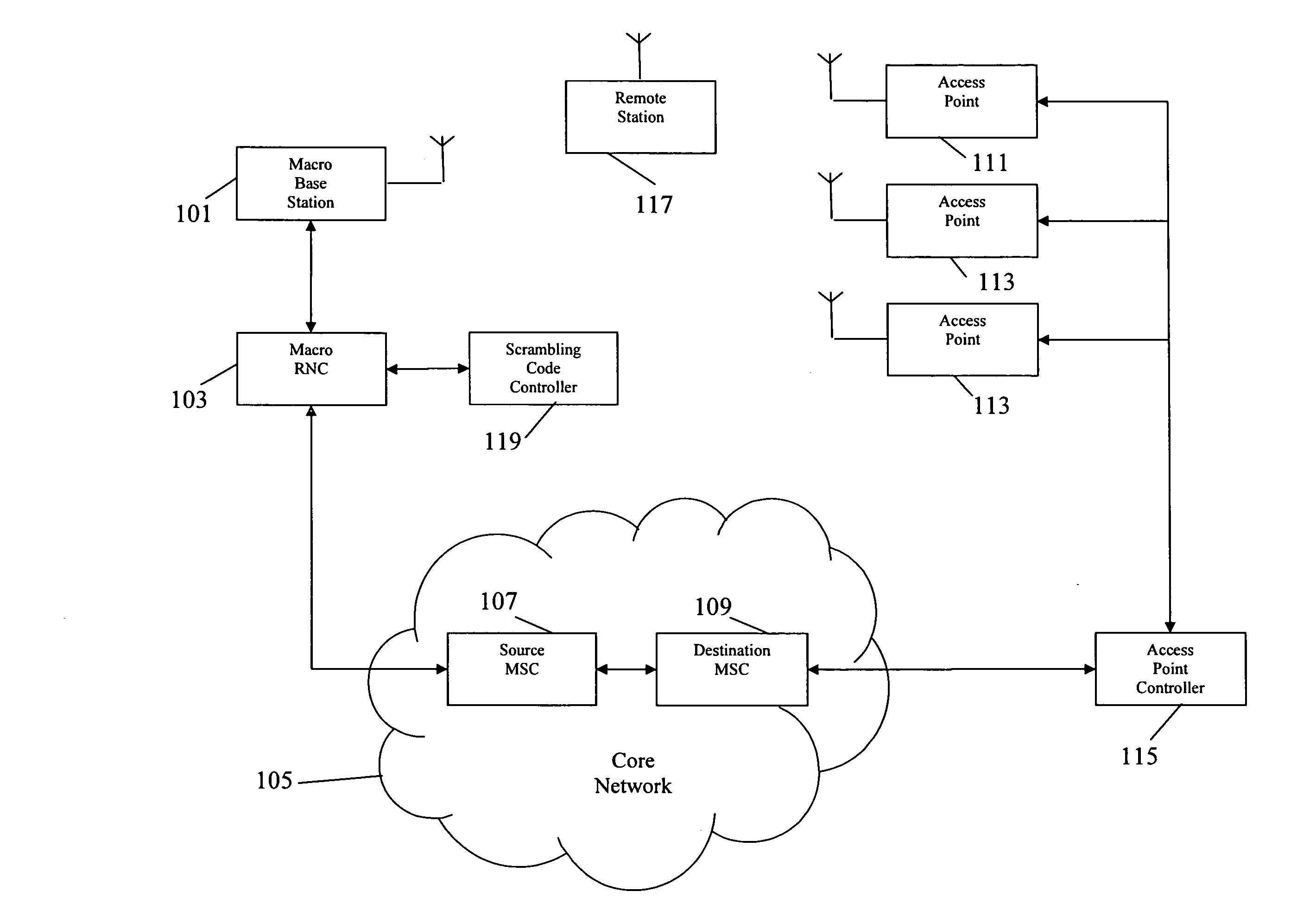
[0027]The following description focuses on embodiments of the invention applicable to a 3rd Generation CDMA (Code Division Multiple Access) cellular communication system such as a Universal Mobile Telecommunications System (UMTS). However, it will be appreciated that the invention is not limited to this application but may be applied to many other cellular communication systems. Also, the description will focus on scenarios where a remote station is handing over from a macro-cell to an underlay cell such as a micro-cell or a pico-cell. However, it will be appreciated that the described principles apply equally to other scenarios including e.g. some scenarios where a handover is made to a macro-cell out of a group of macro-cells using a shared pilot signal scrambling code.

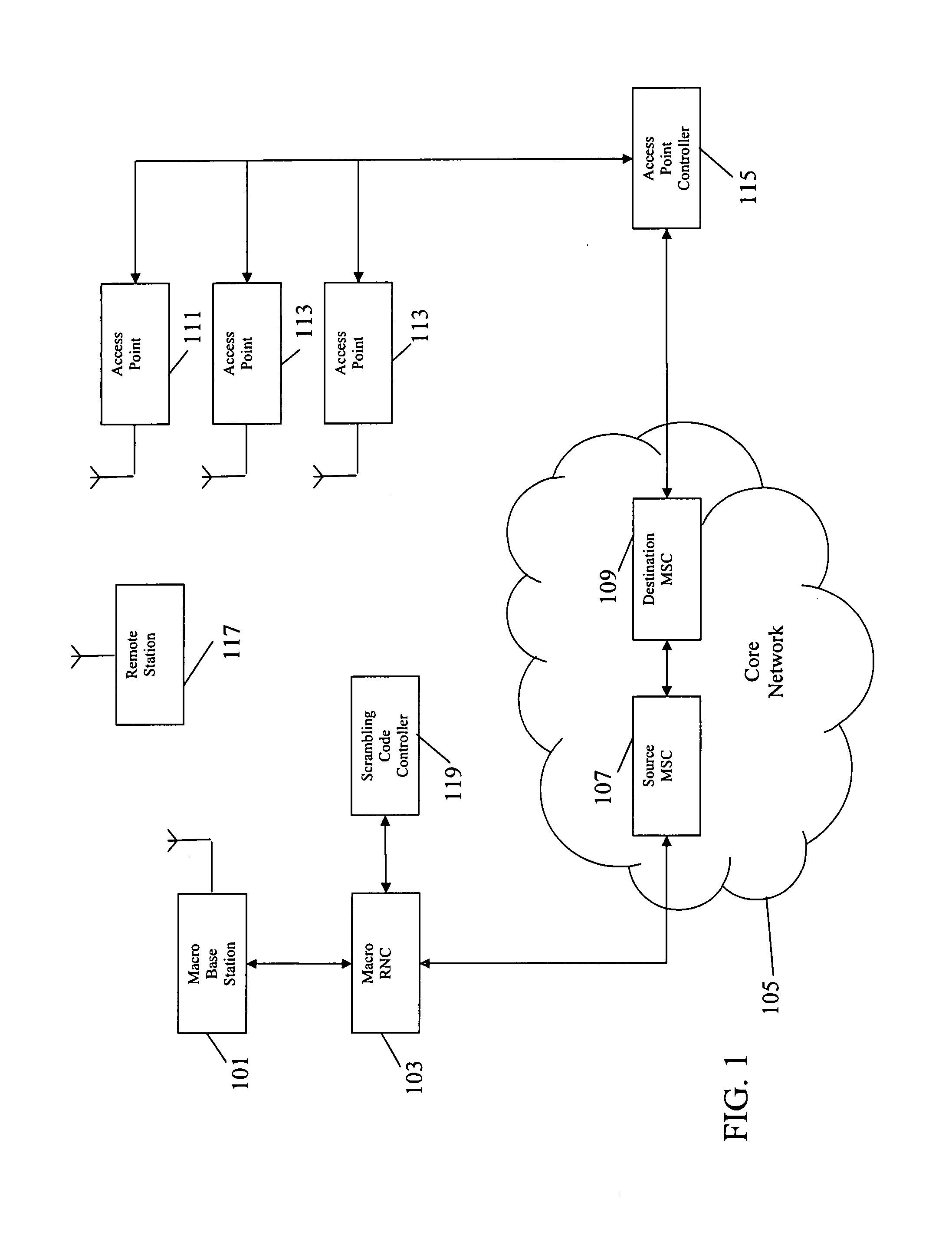
[0028]FIG. 1 illustrates an example of a cellular communication system which in the specific example is a UMTS cellular communication system. In the system, a macro-layer is formed by macro-cells supported by base s...


PUM


Abstract

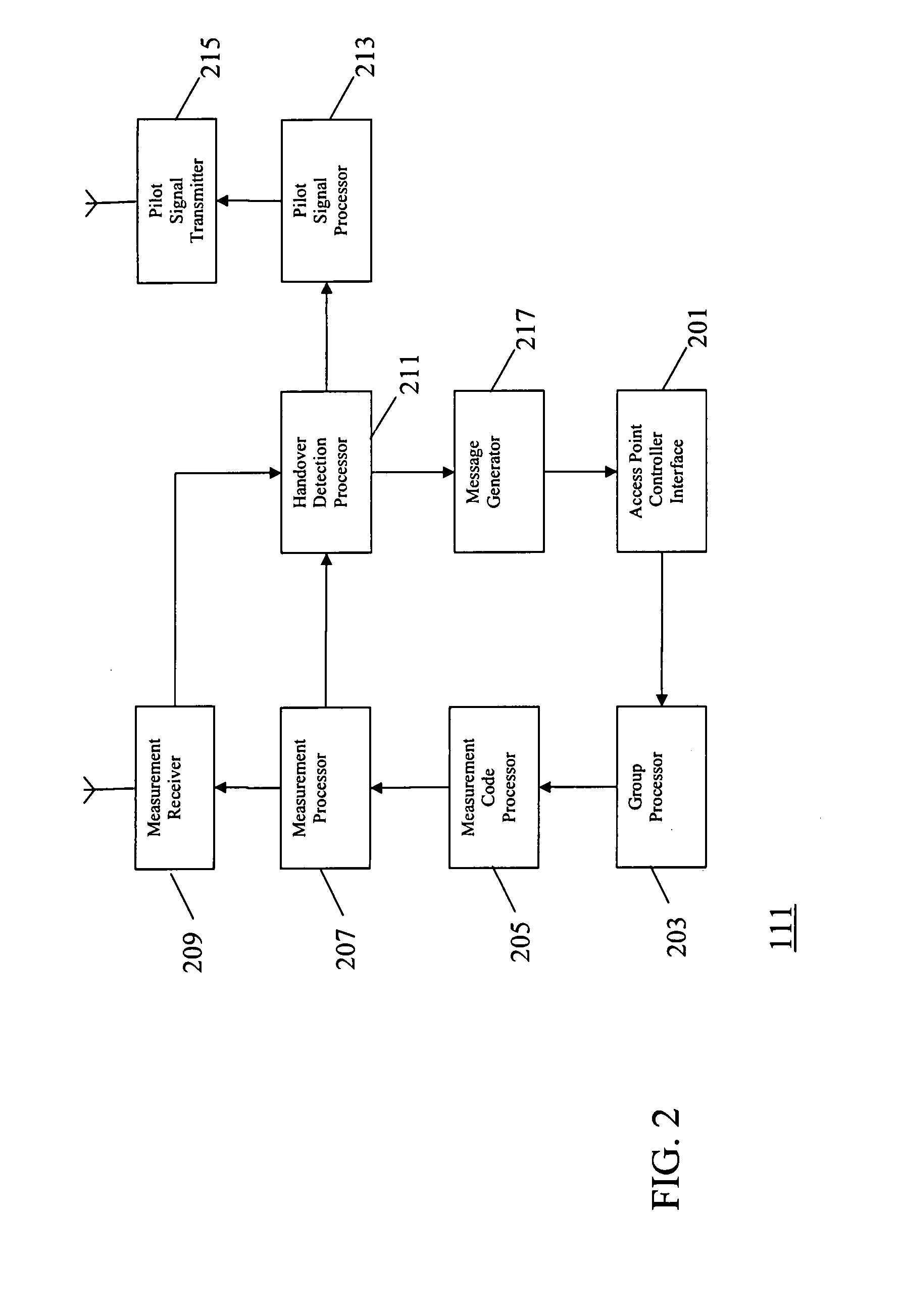
A base station (101) supports a remote station (117) making uplink transmissions using an uplink scrambling code in a first cell. A controller (119) determines a set of uplink scrambling codes from an identity of the remote station (117) and selects the used code therefrom. An access point (111) determines the group of remote stations registered at the access point. A measurement code processor (205) determines the uplink scrambling codes potentially used by the remote stations. A measurement unit (207, 209) then monitors for received signals using these codes and a handover detection processor (211) generates a potential handover detection for the remote station (117) in response to a detection of a received signal using the uplink scrambling code of the remote station (117).

Description

FIELD OF THE INVENTION[0001]The invention relates to a Code Division Multiple Access (CDMA) cellular communication system and in particular, but not exclusively to a Universal Mobile Telecommunication System (UMTS).BACKGROUND OF THE INVENTION[0002]A method which has been used to increase the capacity of cellular communication systems is the concept of hierarchical cells wherein a macro-cell layer is underlayed by a layer of typically smaller cells having coverage areas within the coverage area of the macro-cell. In this way, smaller cells, known as micro-cells or pico-cells (or even femto-cells), are located within larger macro-cells. The micro-cells and pico-cells have much smaller coverage thereby allowing a much closer reuse of resources. Frequently, the macro-cells are used to provide coverage over a large area, and micro-cells and pico-cells are used to provide additional capacity in e.g. densely populated areas and hotspots. Furthermore, pico-cells can also be used to provide ...

Claims


Application Information

Patent Timeline
Patent Type & Authority Applications(United States)
IPC IPC(8): H04W36/00
CPCH04W72/0466H04W36/0083H04W36/00835H04W36/00837H04W36/00
Inventor BARRETT, STEPHEN J.FOSTER, GERALD T.PADFIELD, DAVID C.
Owner GOOGLE TECH HLDG LLC
Learn More