Slittable delivery device assembly for the delivery of a cardiac surgical device

a delivery device and surgical device technology, applied in the field of medical devices and methods, can solve the problems of acceleration or jerk, major procedural delay, and the hub of the delivery catheter typically requires considerably more force to slit through than is required for the sha

Active Publication Date: 2010-04-15
PACESETTER INC
View PDF20 Cites 17 Cited by
  • Summary
  • Abstract
  • Description
  • Claims
  • Application Information

AI Technical Summary

Benefits of technology

[0008]A slittable delivery device for the delivery of a cardiac surgical device is disclosed herein. In one embodiment the delivery device includes a shaft, a hub and a valve bypass assembly. The shaft may be formed of at least a first material. The hub may be coupled to the shaft and may include a wall including a first wall segment and a second wall segment. The first wall segment may include at least the first material and the second wall segment may include at least a second material that is at least one of harder and more rigid than the first material or softer and less rigid than the first material. The valve bypass assembly may be operably coupled to a proximal end of the hub.

Problems solved by technology

However, the hub of the delivery catheter typically requires considerably more force to slit through than is required for the shaft.
As the slitter transitions from the hub to shaft, this force is excessively high and results in an acceleration or jerk.
In the context of an implantable cardiac lead, if this jerk is severe, it may tear the cardiac tissue or disrupt lead placement, which results in a major procedural delay.
Similarly, disruption of other cardiac surgical tools, such as an inner catheter, may cause damage to cardiac tissue or major procedural delays.
Leads or other devices to be passed through the hemostasis valve are often soft and flimsy.
Also, the removal of valve bypass tools known in the art from about an implanted lead can disrupt lead placement.

Method used


Image

  • Slittable delivery device assembly for the delivery of a cardiac surgical device
  • Slittable delivery device assembly for the delivery of a cardiac surgical device
  • Slittable delivery device assembly for the delivery of a cardiac surgical device

Examples


Embodiment Construction

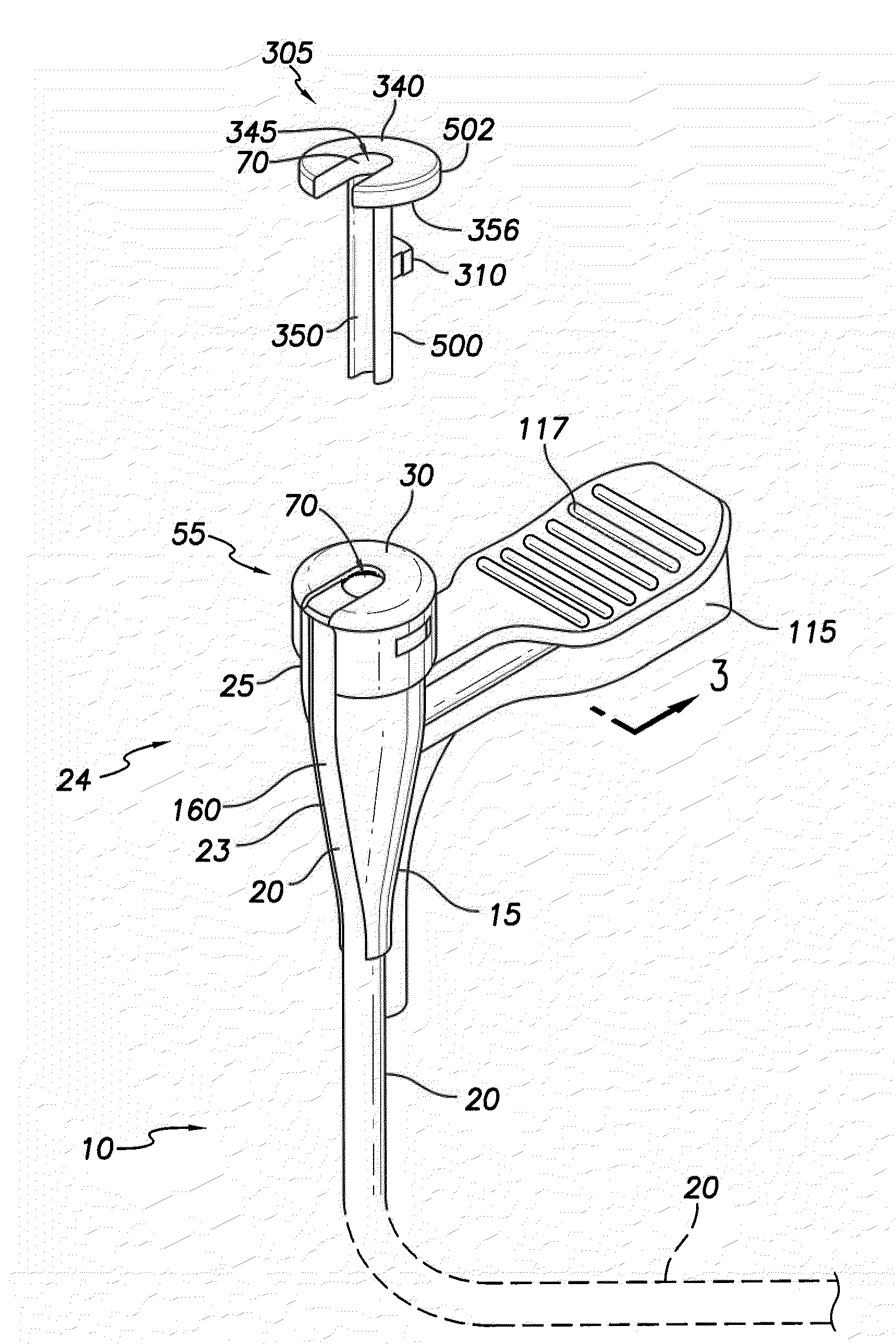
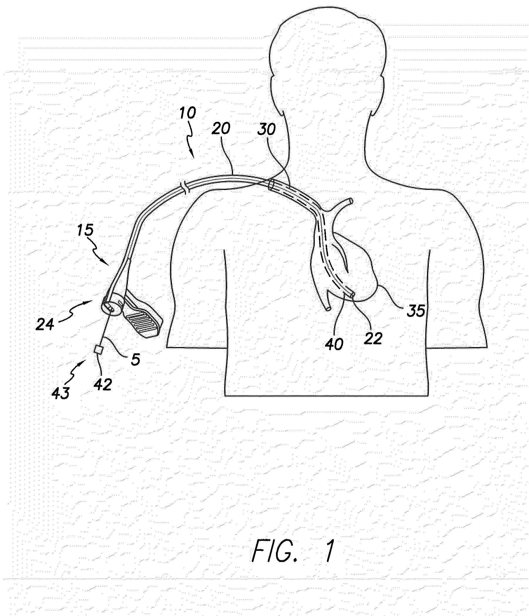
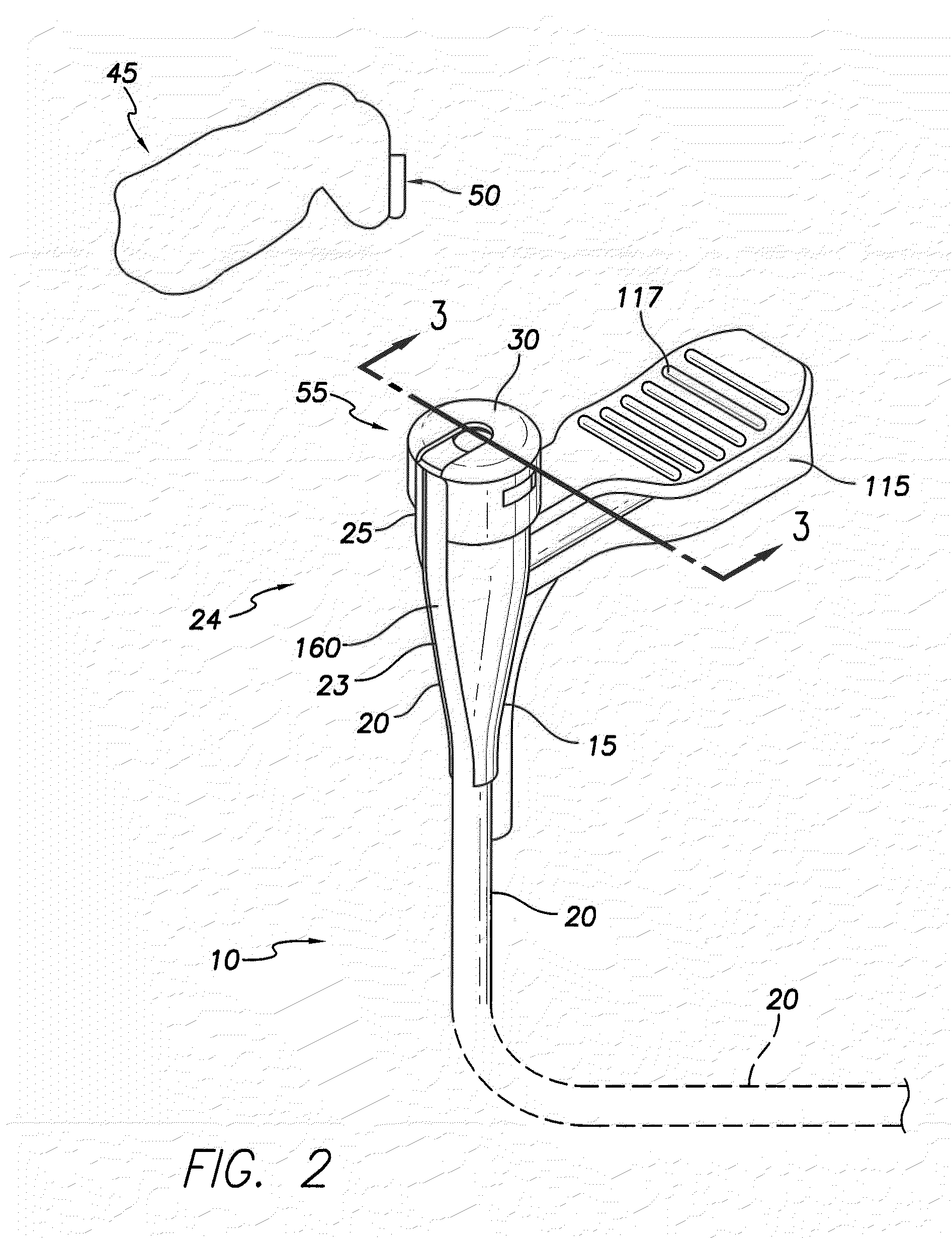
[0049]The present disclosure describes a slittable delivery device 10 for a cardiac surgical device 5, e.g. an implantable medical lead, an inner catheter or outer sheath, a stylet, a guidewire, a sensor or other accessories or devices typically delivered via a catheter or sheath. The delivery device 10 may be a delivery catheter or sheath 10 having a tubular shaft 20 and a hub 15 on a proximal end 24 of the device 10. The delivery device 10 includes a lumen extending the length of the delivery device 10 and which provides a passageway for the surgical device 5 to enter the body, for example, the heart during implantation of a lead 5. Upon placement of the surgical device 5, the delivery device 10 is removed from about the surgical device 5 via slitting of the delivery device 10 along its length.

[0050]In one embodiment, the tubular shaft 20 is integrated into the hub 15 such that a wall 7 of the shaft 20 forms a longitudinally extending strip of the wall 125 of the hub 15 the entire...


PUM

PropertyMeasurementUnit
lengthsaaaaaaaaaa
forceaaaaaaaaaa
softaaaaaaaaaa

Abstract

An assembly for the delivery of a cardiac surgical device is disclosed herein. In one embodiment, the assembly includes a slittable delivery device and a bypass assembly. The slittable delivery device may include a hub, a shaft integrated into the hub and forming at least a segment of the circumferential surface of the hub, and a hemostasis valve contained substantially within the hub. The bypass assembly may include a cap and a valve bypass tool. The cap may be on a proximal end of the hub and may include an opening in the cap extending radially outward from a point near a radial center of the cap through a circumferential edge of the cap. The valve bypass tool may be operably coupled to the cap and may include a longitudinally extending open channel.

Description

CROSS REFERENCE TO RELATED APPLICATIONS[0001]This application is a continuation-in-part (“CIP”) of U.S. application Ser. No. 12 / 248,802, filed Oct. 9, 2008, entitled “Slittable Delivery Device for the Delivery of a Cardiac Surgical Device,” and is incorporated by reference herein in its entirety.FIELD OF THE INVENTION[0002]The present invention relates to medical apparatus and methods. More specifically, the present invention relates to delivery device assemblies for cardiac surgical devices, such as implantable cardiac electrotherapy leads, guidewires, inner catheters, outer sheaths, and other accessories, methods of manufacturing such delivery device assemblies and kits including the same.BACKGROUND OF THE INVENTION[0003]Implantable pulse generators, such as pacemakers, defibrillators or implantable cardioverter defibrillators (“ICD”) provide electrotherapy to cardiac tissue via implantable cardiac electrotherapy leads. Delivery devices, such as delivery catheters or sheaths, are ...

Claims


Application Information

Patent Timeline
Patent Type & Authority Applications(United States)
IPC IPC(8): A61M25/01B65D71/00
CPCA61M25/0097A61M25/0668A61M2039/066A61M2039/062A61M2039/0633A61M39/0606
Inventor HELGESON, HEATHERPRICE, DALEHASTINGS, JOHNSWANSON, BRIANMARKS, ROSS
Owner PACESETTER INC
Why Eureka
Try Eureka