Surgical bone milling instrument

a bone milling and instrument technology, applied in the field of surgical bone milling instruments, can solve the problems of limiting the height of bone and compromising the success of sinus cavity filling,

Inactive Publication Date: 2010-04-15
C G M CO LTD
View PDF11 Cites 37 Cited by
  • Summary
  • Abstract
  • Description
  • Claims
  • Application Information

AI Technical Summary

Benefits of technology

[0026]Furthermore, since the axial penetration of the instrument along the bone cavity is directly dependent on the angle of rotation o

Problems solved by technology

The insertion of dental implants in the rear areas of the upper jaw is almost always conditioned by the presence of the maxillary sinus, which limits the availability of bone in height, especially in patients who have been edentulous for a long time.
The main difficulty of these techniques for raising the maxillary sinus is the creation of the final part

Method used


Image

  • Surgical bone milling instrument
  • Surgical bone milling instrument
  • Surgical bone milling instrument

Examples


second embodiment

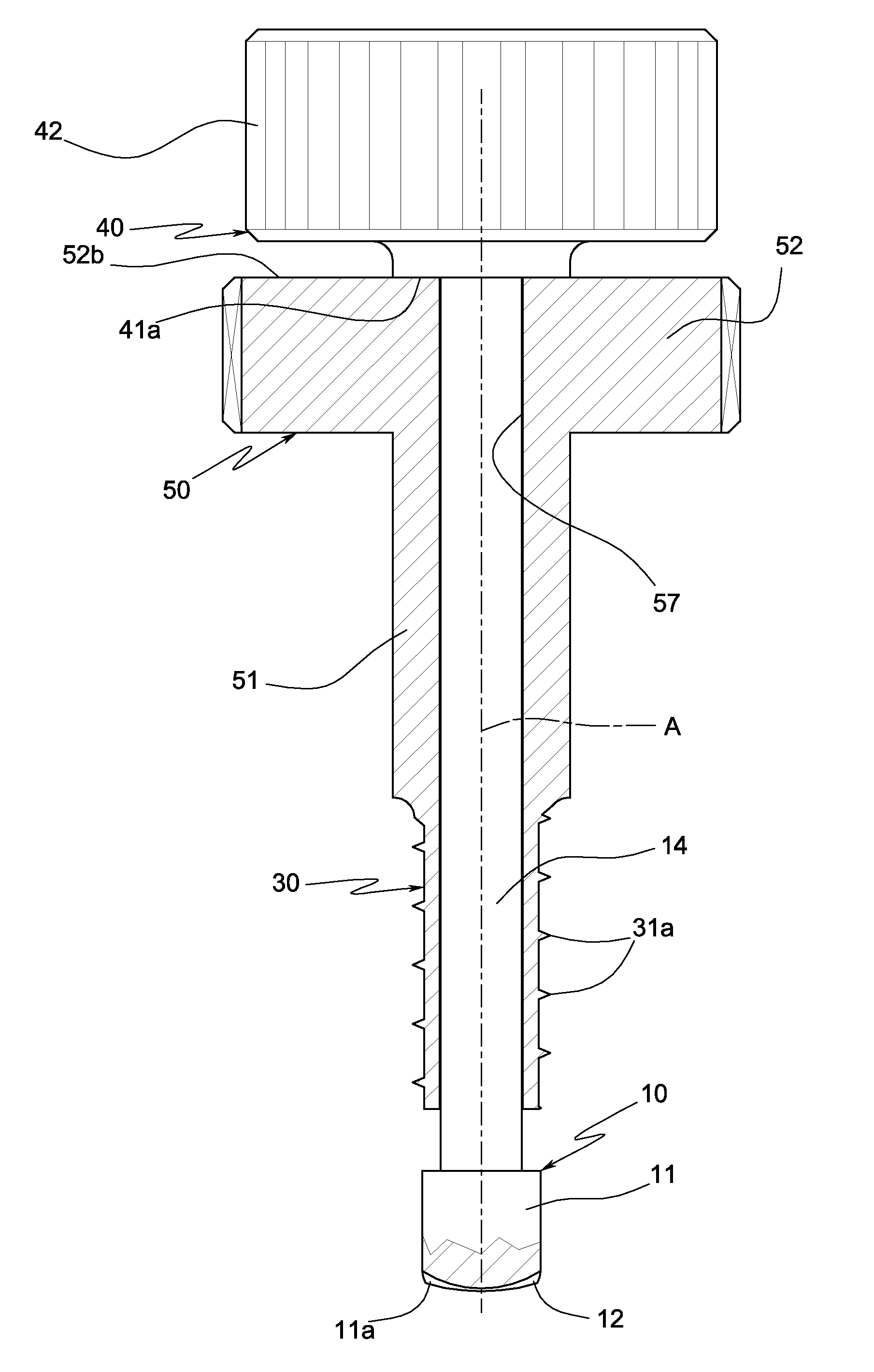
[0064]This second embodiment differs from the first principally due to the fact that the drive element 40 rotates only the milling element 10 and not the tubular element 30 too; consequently the described profiled raised portions 35 and 45 are absent and the drive element 40 can rotate freely relative to the tubular element 30. The tubular element 30 is instead rotated by a dedicated second drive element 50, independent of the first drive element 40.

[0065]In particular the drive element 50 is located forward of the drive element 40 and is coaxially and solidly fixed to the rear end portion of the tubular element 30; the rod 14 of the milling element 10 passes through a matching axial through-hole 57 formed in the drive element 50.

[0066]The second drive element 50 comprises a tubular shank 51 fixed coaxially and solidly to the rear end portion of the tubular element 30 and a rear portion 52, of greater diameter relative to the shank 52, shaped as a circular handle that enables the op...

first embodiment

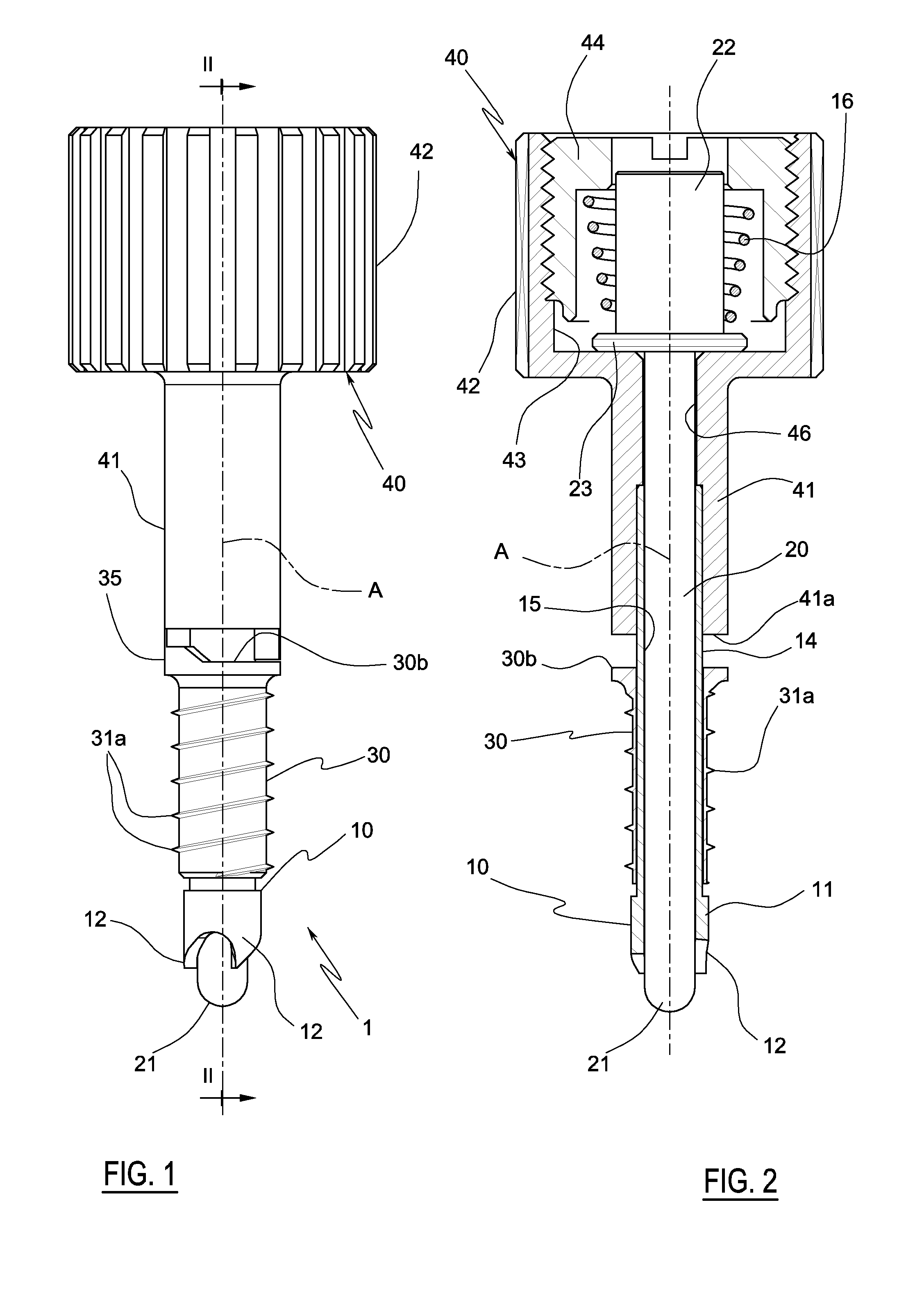
[0080]In the instrument, the rotation of the tubular element 30 is produced by manually rotating the drive element 40, which transmits, through the reciprocally engaging elements 35 and 45, a torque to the tubular element 30.

[0081]In the second embodiment of the instrument, the rotation of the tubular element 30 is produced by manually rotating the drive element 50, which drives only the element 30; the milling head 11 is not set in rotation.

[0082]In the second phase (milling phase), only the milling element 10 is rotated and it is moved axially forward relative to the tubular element 30 to excavate, in the axial direction, a cavity on the bottom of the hole 71 (see FIG. 6B).

[0083]If the raised milling ridges 12 have a limited radial extension, for example due to the presence of the hole 15 in the head 11 (FIGS. 1-8), the cavity that they create has the form of a peripheral circular groove 73 with a maximum axial depth of D (FIG. 6C), which develops along the circumference of the su...


PUM


Abstract

A surgical bone milling instrument, suited to operate in a hole formed in a bone, comprising a milling element (10), with longitudinal axis (A) and with the forward end portion (11) rotating around a longitudinal axis (A), and milling the bone. The instrument comprises a tubular element (30) of circular external cross-section and provided with a thread engaging, by helical coupling, a hole formed in the bone. The milling element (10) is associated with the tubular element (30), arranged so that the forward end portion (11) thereof is located ahead of the tubular element (30) and can rotate around the longitudinal axis (A) thereof and translate axially relative to the tubular element (30). The milling element (10) has a rear portion (14) which passes coaxially through the tubular element (30), while the forward end portion (11) projects beyond the front of the tubular element (30). The milling procedure of a bone cavity can be completed while maintaining control of the position of the device relative to the hole. Furthermore, in each phase in which the milling element is rotated, while the instrument is axially stationary inside the hole, a groove is created on the end of the hole (or an extension of the entire hole) the depth of which is constant and predetermined. Further, by way of axial pressure applied to the milling head by the drive element, a detachment of residual bone wall can be achieved as soon as this has reached a breaking resistance which is lower than a force applied by the drive element.

Description

TECHNICAL FIELD [0001]The present invention is a surgical bone milling instrument.BACKGROUND ART [0002]In general, the purpose of the instrument is the removal of areas of bone in a controlled manner in proximity to delicate parts of bone, typically to complete holes in bones in which the a terminal portion of the hole is located close to particularly delicate organs.[0003]A typical application is in the surgical technique of mini-lifting of the maxillary sinus cavity, which involves the raising of the floor and filling with biomaterial of the maxillary cavity through a hole prepared in the bone for the insertion of a dental implant.[0004]The cavity in the maxillary sinus is the largest of the pneumatic cavities in the cranial bone and it is located in the rear areas above the upper jaw.[0005]The formation of the floor of the maxillary sinus can be influenced by the presence of the roots of premolar and molar teeth. At the apex of these roots there is a thin layer of compact cortica...

Claims


Application Information

Patent Timeline
IPC IPC(8): A61B17/00
CPCA61B17/1633A61B17/1637A61B17/1673A61B17/1688A61B17/176A61C1/082A61B2017/00477A61B2017/349A61B2019/306A61B2019/462A61B17/864A61C8/0092A61B2090/036A61B2090/062
Inventor PARMIGIANI, CORRADO SAVERIO
Owner C G M CO LTD
Why Eureka
Try Eureka