Tool recognition with profinet

a tool recognition and profinet technology, applied in the field of activating an automation station, can solve problems such as the need for tool coding

Active Publication Date: 2010-04-15
PHOENIX CONTACT GMBH & CO KG
View PDF29 Cites 5 Cited by
  • Summary
  • Abstract
  • Description
  • Claims
  • Application Information

AI Technical Summary

Benefits of technology

[0017]The solution of the problem according to the invention is a method with the characteristics of Claim 1.

Problems solved by technology

Essential disadvantages of the above-described prior art are based on the necessary tool coding.
Moreover, the respective coding units can become contaminated or be destroyed in continuous operation, which may cause downtime.

Method used


Image

  • Tool recognition with profinet
  • Tool recognition with profinet

Examples


Embodiment Construction

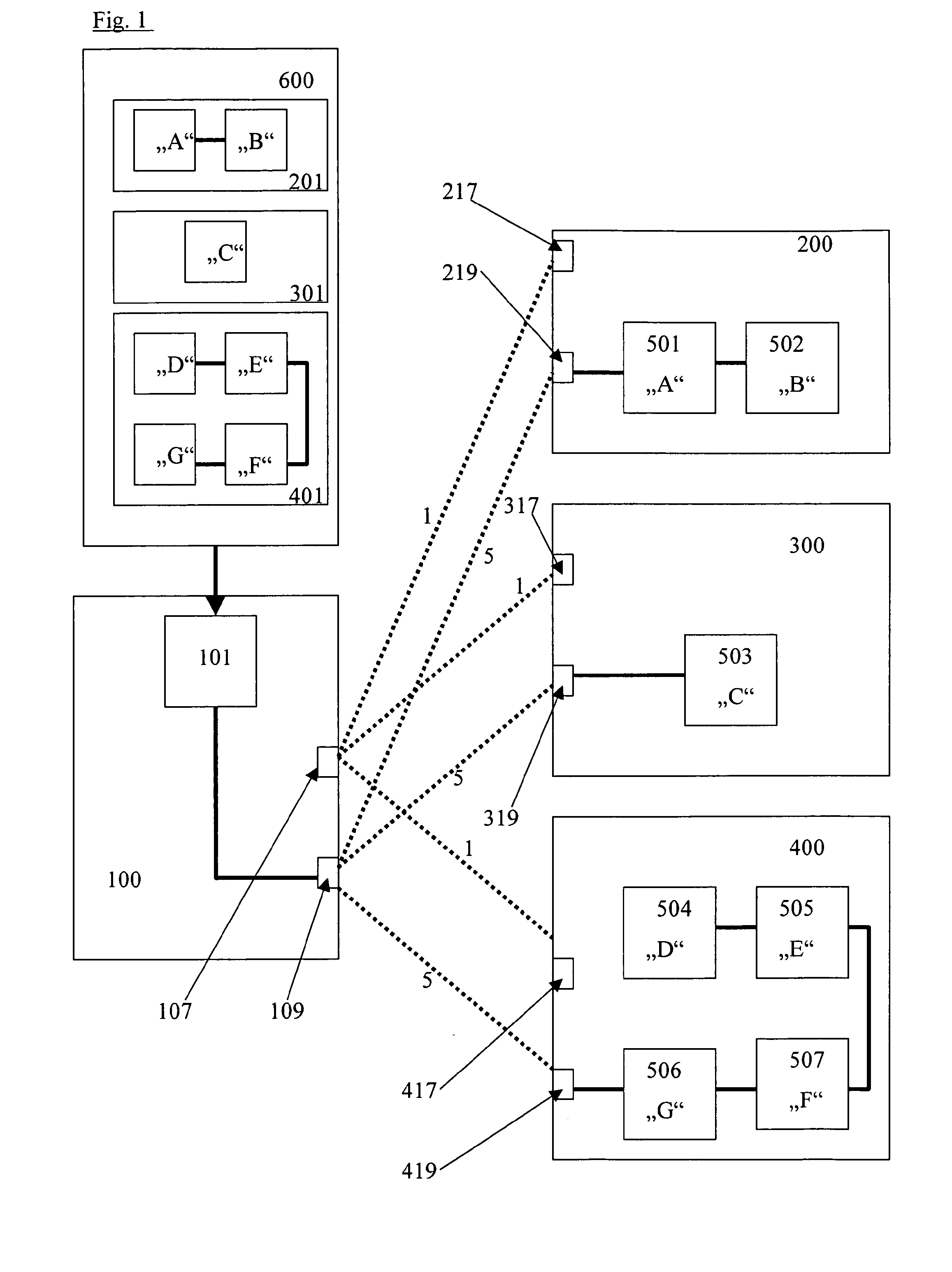
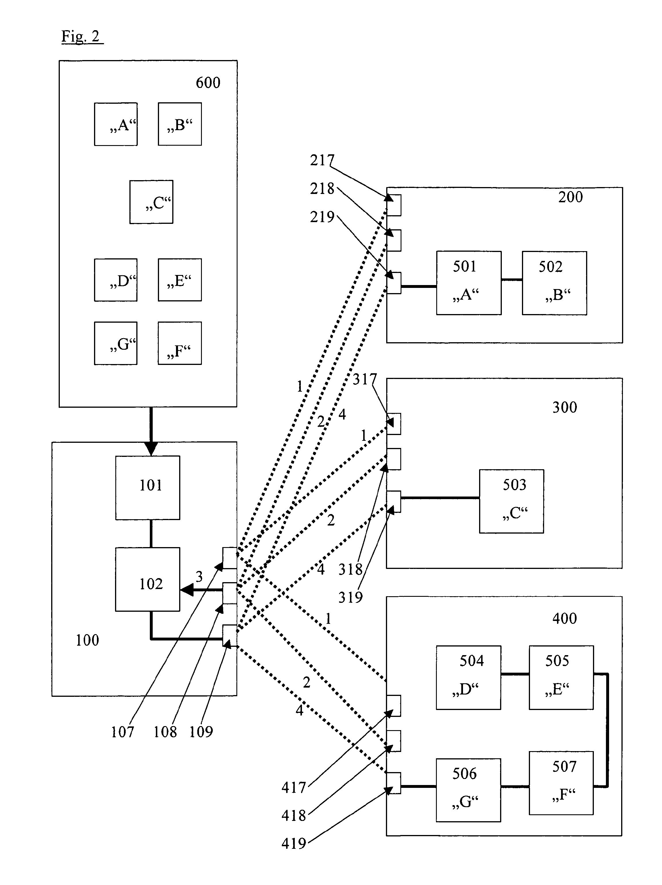
[0025]Similarly to FIG. 2, FIG. 1 shows an exemplary automation apparatus 100, which is adapted to operate according to the Profinet standard and to which a configuration unit 600 is assigned. Three tools 200, 300 and 400 are to be connected as automation stations to the automation apparatus 100 in the operation, wherein again a number of Profinet-compatible field devices 501 and 502, 503 and 504-507, which can be different in number and type and are generally also necessary, are installed in tools 200, 300 and 400.

[0026]First, essentially as in the prior art, the tools 200, 300 and 400 are coupled to the device 100. In the physical coupling process of tools 200, 300 and 400, the latter are supplied in a first step with power 1 via a supply unit 108 arranged on the automation device 100 and via supply units 217, 317 and 417 arranged on the tools.

[0027]The field devices 501 and 502, 503 and 504-507 are also supplied with power via the supply voltage of the tools 200, 300 and 400, whi...


PUM


Abstract

The invention relates to a method for activating an automation station in the automation apparatus of an industrial application.The invention provides a method for activating an automation station (200, 300, 400) in the automation apparatus (100) of an industrial application, in which the automation station comprises a plurality of Profinet-compatible devices (501, . . . , 507) to which an unambiguous symbolic name is provided for identification, and wherein an identification of the automation station connected to the automation apparatus for operation is performed based on the symbolic names of the Profinet-compatible devices, and the Profinet-compatible devices are driven by the automation apparatus after connection of the automation station in functional dependence on the identified automation station.

Description

FIELD ON THE INVENTION[0001]The invention relates to a method for activating an automation station in the automation apparatus of an industrial application.BACKGROUND OF THE INVENTION[0002]In modern industrial applications such as automobile manufacturing or mechanical engineering, it is frequently necessary to be able to operate different tools on an apparatus in the plant, with field devices such as sensors or actuators that are necessary for tool functionality.[0003]Profinet, which is well known to be the open Ethernet-based automation standard of the Profibus User Organization (PNO) and follows the Ethernet standard (according to IEEE 802.3) essentially 100%, is currently used generally for linking or integrating field devices in automation systems of industrial applications. Process and production data are available not only here on the field level, they can also be seamlessly integrated into multi-division data acquisition systems, thus enabling integration of the decentralize...

Claims


Application Information

Patent Timeline
Patent Type & Authority Applications(United States)
IPC IPC(8): G05B11/01
CPCG05B19/0423G05B2219/25009G05B2219/31134G05B2219/25061G05B2219/25428G05B2219/25057
Inventor LESSMANN, GUNNAR
Owner PHOENIX CONTACT GMBH & CO KG
Why Eureka
Try Eureka