Method and apparatus for determining the flow parameters of a streaming medium

Active Publication Date: 2010-04-22
USCOM
View PDF15 Cites 79 Cited by
  • Summary
  • Abstract
  • Description
  • Claims
  • Application Information

AI Technical Summary

Benefits of technology

[0026]When used as a spirometer, it may be advantageous that the conduit has a working position with the

Problems solved by technology

Measuring only one frequency change has the same drawback as measuring a change of one transit time, it results in a dependency on sound velocity.
A further problem arises however when continuous waves are used, which cause unintended interferences of reflected waves and the forming of standing waves which deteriorate the overall result of measurement.
When using different frequencies, it might be difficult to avoid unint

Method used


Image

  • Method and apparatus for determining the flow parameters of a streaming medium
  • Method and apparatus for determining the flow parameters of a streaming medium
  • Method and apparatus for determining the flow parameters of a streaming medium

Examples


Embodiment Construction

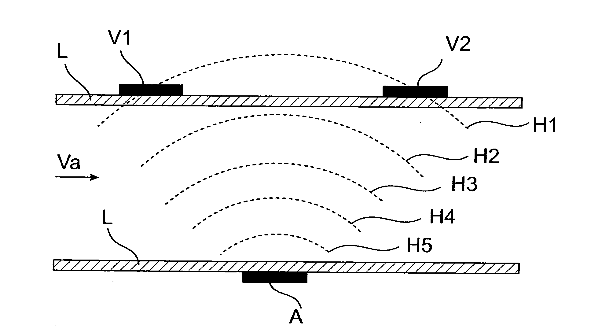
[0048]A first aspect of the invention can be understood best with reference to FIG. 1 showing a conduit L in cross section with a medium streaming with a flow rate va. The a conduit may be configured to have a circular or angular, symmetrical or asymmetrical, flat or oblate cross sectional shape at least in the measuring area. The cross sectional area should be generally constant along the longitudinal direction of the conduit but in some applications it may also be decreased in the measuring area in order to increase the flow speed and therefore increase the resolution and the accuracy of the measurement. The conduit is provided on the outer surface with a transducer configured as a transmitter A for generating the longitudinal waves and for transmitting the waves along two diagonal transmission paths through the streaming medium in an upstream and a downstream direction. On the outer surface of the conduit on an opposite side relative to the transducer configured as a transmitter ...


PUM


Abstract

According to the method longitudinal waves are generated in a transducer used only as a transmitter connected from outside to a conduit. These waves are transmitted along two diagonal paths through the streaming medium in an upstream and a downstream direction, and received by two transducers used only as receivers which are located in a diagonal upstream and downstream position and on an opposite side relative to the transducer used as a transmitter, also connected to the conduit. A transit time value of the waves between the transducer used as a transmitter and each of the transducers used as receivers is determined. A difference value on the basis of the determined transit time values is generated and the flow parameters are determined on the basis of said difference value. This measuring method is highly independent of the propagation velocity of the wave in the medium streaming in the conduit therefore also independent of the temperature and humidity of a gaseous medium. An apparatus and a conduit for use in the apparatus for performing the method is also suggested. The conduit used in the apparatus comprises a first location for receiving a transmitter in a middle region of the measuring area and two second locations for receiving receivers in a border region of the measuring area opposite to the first location. The wall of the conduit is dimensioned so that the longitudinal waves can pass through it with minimal loss and maximum efficiency. The inner wall of the conduit forms a uniform and continuos surface for the transmission of the longitudinal waves between the transmitter and the receivers and for blocking the passage of any organic or inorganic material. In medical applications the apparatus and its housing is configured to receive, hold and release a sterile conduit.

Description

TECHNICAL FIELD[0001]The invention relates to a method for determining the flow parameters of a streaming medium in a conduit. Such flow parameters include for example flow rate or speed, volume or mass flow rate or other parameters. The invention also relates to an apparatus for performing the above method for determining the flow parameters of a streaming medium in a conduit. The streaming medium according to the invention may be any gas or fluid or a mixture of different gases or fluids. In a special application the streaming medium is air which can be defined as a mixture of gases also comprising a certain amount of fluid in a vaporized form.BACKGROUND ART[0002]There are different methods known in the art for determining the flow rate or other different flow parameters. One group of devices to accomplish this task comprise moving mechanical elements such as rotors or the like. Another group of devices comprises instead of the moving mechanical elements at least one pair of trans...

Claims


Application Information

Patent Timeline
IPC IPC(8): G01F1/66
CPCG01F1/66G01F1/662G01F25/0007G01F15/14G01F1/667G01F25/10
Inventor FERENCZ, GYORGYROZSNYIK, ZOLTAN
Owner USCOM
Why Eureka
Try Eureka