Tweezers with gripping elements mounted swivelling on branches

a technology of swivelling tweezers and gripping elements, which is applied in the field of pair of tweezers, can solve the problems of not being able to do the same with tweezers, requiring a great deal of vigilance and dexterity from operators, and achieving the effect of convenient handling

Inactive Publication Date: 2010-04-22
COMMISSARIAT A LENERGIE ATOMIQUE ET AUX ENERGIES ALTERNATIVES
View PDF6 Cites 18 Cited by
  • Summary
  • Abstract
  • Description
  • Claims
  • Application Information

AI Technical Summary

Benefits of technology

[0005]The object of the invention is to provide a pair of tweezers that are easy to handle and that do not present the drawbacks of the prior art.

Problems solved by technology

Handling of microelectronic components with such tweezers requires a great deal of vigilance and dexterity from the operators.
Moreover, if the environment changes in the course of handling, it is impossible to do the same with the tweezers.

Method used


Image

  • Tweezers with gripping elements mounted swivelling on branches
  • Tweezers with gripping elements mounted swivelling on branches
  • Tweezers with gripping elements mounted swivelling on branches

Examples


Embodiment Construction

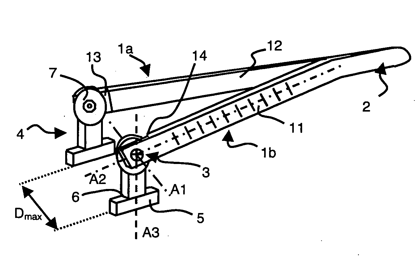
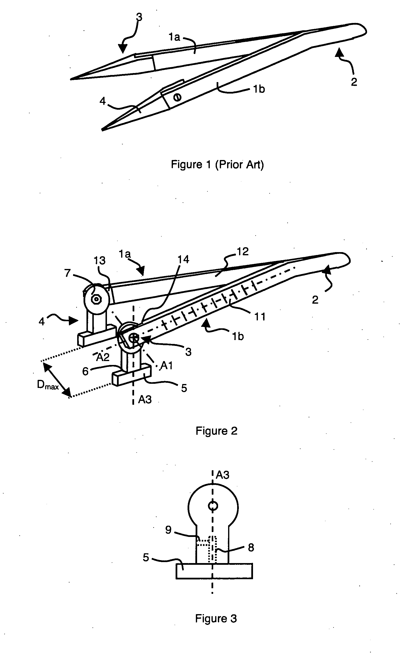
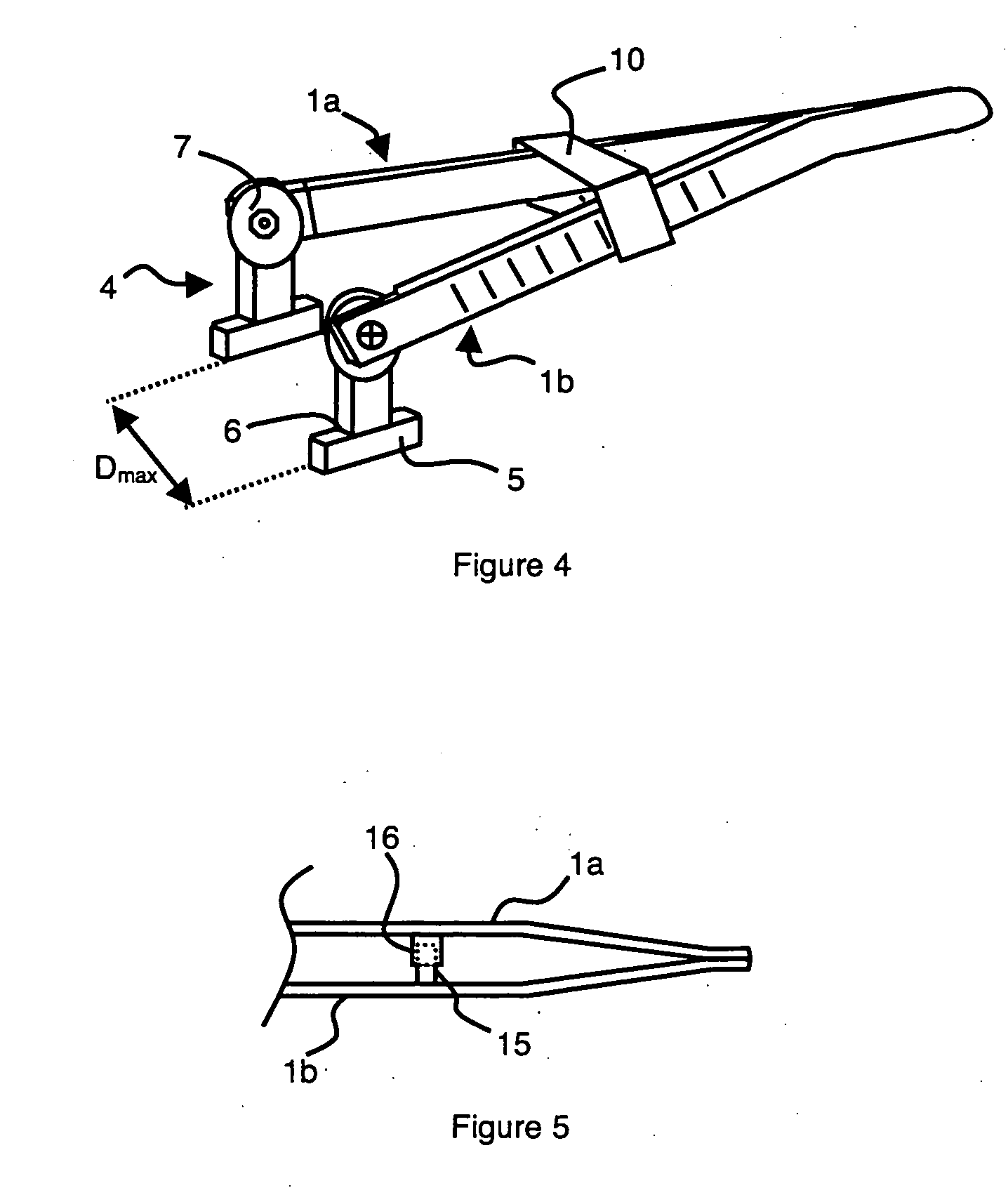
[0014]As illustrated in FIG. 2, the tweezers comprise two branches 1a and 1b joined to one another at a first end 2. A second end 3 of each branch 1a and 1b comprises a gripping element 4 mounted rotating freely around a swivel axis A1 on the second end of the corresponding branch 1a or 1b. Swivel axis A1 is preferably perpendicular to a longitudinal axis A2 of the branch.

[0015]Branches 1a and 1b have a set elasticity enabling the gripping means to be separated by a maximum distance Dmax when no stress is applied on branches 1a and 1b. Therefore, as gripping elements 4 are facing one another, by exerting a sufficient pressure on the branches, an operator can move the latter towards one another to pick up a chip. After he has picked the chip up and moved it, the operator can release the pressure and the tweezers revert to their original shape while at the same time releasing the chip.

[0016]As illustrated in FIG. 2, the gripping element of each branch preferably comprises a longitudin...


PUM


Abstract

The tweezers comprises two branches joined at a first end, a second end of each branch comprising a gripping element. The gripping element of each branch is mounted rotating freely around a swivel axis at the second end of said branch. The gripping element of each branch comprises a longitudinal axis perpendicular to the corresponding swivel axis, and a pad is fixed to a free end of said gripping element perpendicularly to said longitudinal axis of the gripping element.

Description

BACKGROUND OF THE INVENTION[0001]The invention relates to a pair of tweezers comprising two branches joined at a first end, a second end of each branch comprising a gripping element, said gripping element of each branch being mounted rotating freely around a swivel axis at the second end of said branch.STATE OF THE ART [0002]Tweezers are designed for handling fragile objects. They have an application in microelectronics where they are used as gripping and handling tool for microelectronic components such as chips. In this type of use, it is necessary to avoid any risk of damaging the edges and the active top surface of the chip on which low-profile circuitry, for example as on CMOS chips or infrared detectors, or raised-profile circuitry, such as for example die-matrix chips, can be located.[0003]As illustrated in FIG. 1, the tweezers commonly used comprise two branches 1a and 1b joined to one another at a first end 2. A second end 3 of each branch 1a and 1b comprises a gripping ele...

Claims


Application Information

Patent Timeline
Patent Type & Authority Applications(United States)
IPC IPC(8): B25B9/02
CPCG04D1/021B25B9/02
Inventor AIT-MANI, ABDENACER
Owner COMMISSARIAT A LENERGIE ATOMIQUE ET AUX ENERGIES ALTERNATIVES
Why Eureka
Try Eureka