Lighting device

a technology of light source and light source, which is applied in the direction of semiconductor devices for light sources, coupling device connections, lighting and heating apparatus, etc., can solve the problems of insufficient design consideration for resolving heat-related problems, damage and degradation of leds themselves and boards, and insufficient leds, etc., to achieve easy attachment to the heat-resisting part, prevent the effect of a larger size of lighting devices and elasticity

Active Publication Date: 2010-04-22
SHARP KK
View PDF6 Cites 203 Cited by
  • Summary
  • Abstract
  • Description
  • Claims
  • Application Information

AI Technical Summary

Benefits of technology

[0012]The present invention has been devised in view of such situations. An object thereof is to provide a lighting device in which a structure for radiating heat from the LED is provided under the condition that arrangement of a drive circuit section driving an LED is optimized so that size increase in the lighting device is prevented. Another object is to provide a lighting device capable of preventing a situation that dust, particulates, or the like go into contact with the drive circuit section so as to cause ignition or a fault.
[0027]According to the present invention, under the condition that size increase in the lighting device is prevented, heat radiation from the LED is achieved effectively. Further, occurrence of ignition or a fault is avoided that may be caused when the drive circuit section driving the LED goes into contact with dust, particulates, or the like.

Problems solved by technology

As such, when LEDs are accumulated at high densities, a problem arises that heat generated by the LEDs themselves causes damage and degradation in the LEDs themselves and the board on which the LEDs are mounted.
Nevertheless, in the LED bulb described in Japanese Patent Application Laid-Open No. 2001-243807 and the LED unit with base described in Japanese Patent Application Laid-Open No. 2005-216495, design consideration for resolving such a problem caused by heat generated by the LED is insufficient.
The LED bulb and the LED unit with base described in the above-mentioned Japanese Patent Application Laid-Open No. 2001-243807 and Japanese Patent Application Laid-Open No. 2005-216495 constitute a part of the prior art concerning a lighting device employing an LED as a light source, but do not resolve the problem caused by heat generated by the LED.
Nevertheless, in the prior art described in the above-mentioned Japanese Patent Application Laid-Open No. 2001-243807 and Japanese Patent Application Laid-Open No. 2005-216495, design consideration for resolving such a problem caused by heat generated by the LEDs is insufficient.
Nevertheless, the ratio of the volume occupied by the heat sink to the overall volume of the lighting device is extremely high.
This causes size increase in the lighting device and, in some cases, impairs the external appearance of the lighting device.
Thus, when the lighting device is used for a long time, dust, particulates, or the like enter the recess from the outside and go into contact with the power supply circuit so as to cause ignition or a fault in some cases.
This causes a problem that a sufficient space is not ensured for adapting an increase in the number or the size of circuit components caused in association with an increase in the power consumption of the lighting device.
This also contributes to radiation of the heat from the drive circuit section.

Method used


Image

  • Lighting device
  • Lighting device
  • Lighting device

Examples


embodiment 1

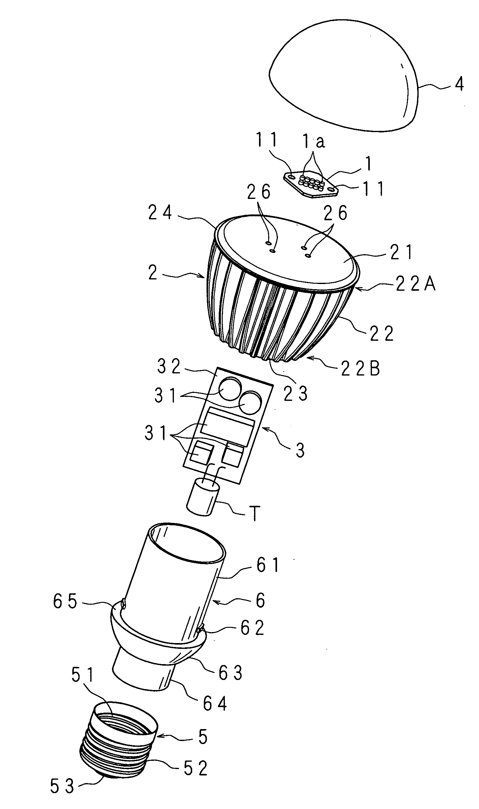
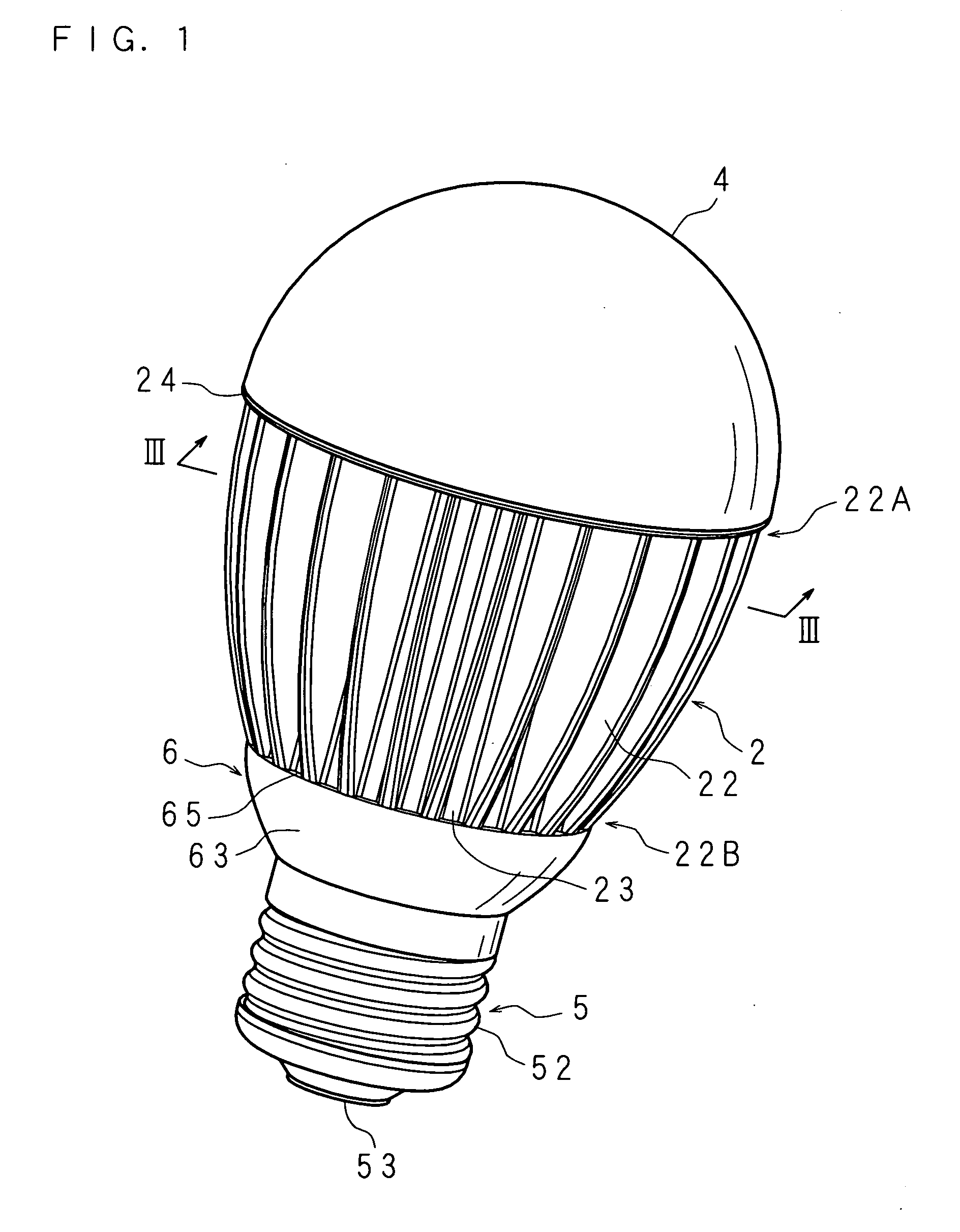
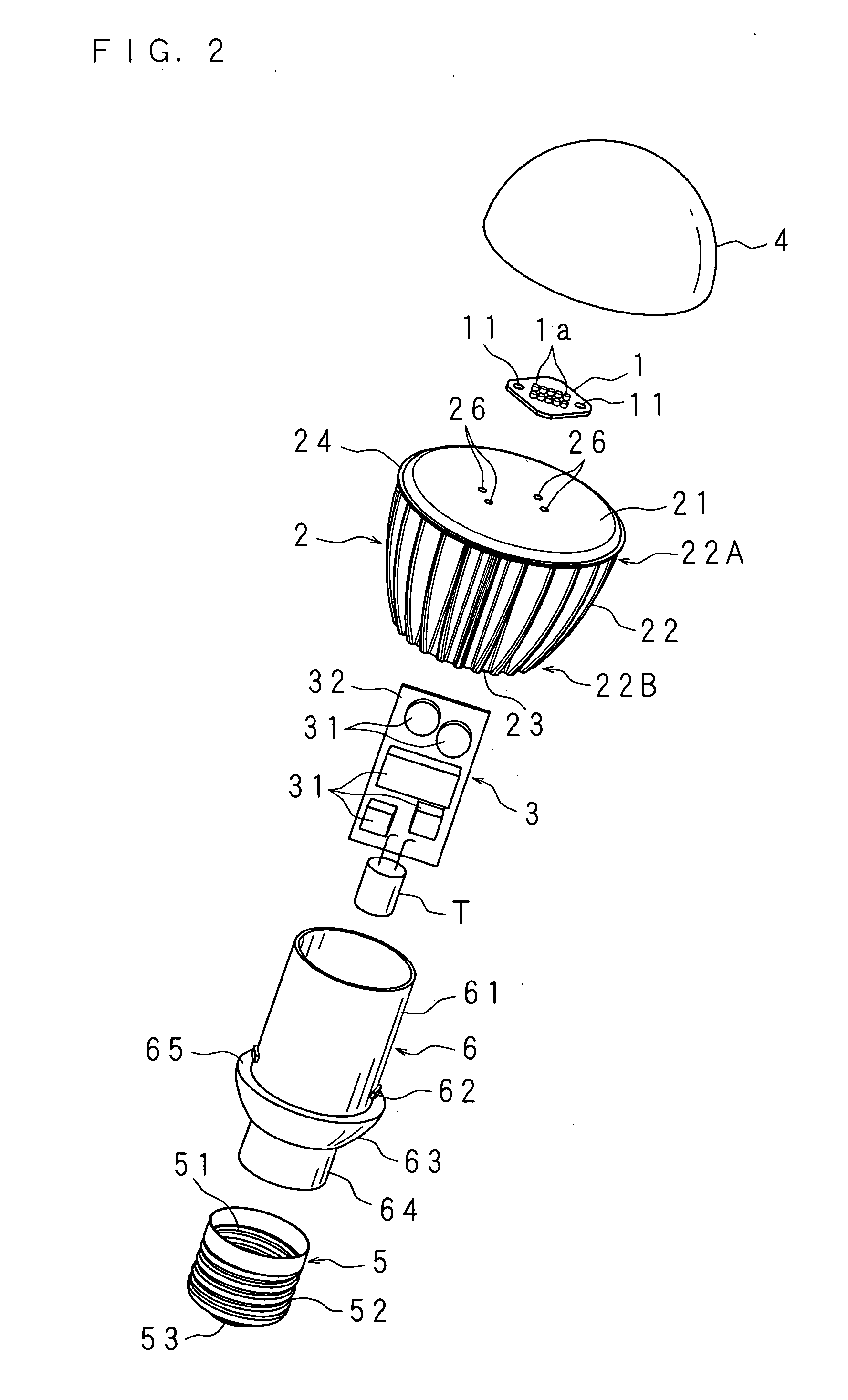
[0053]Embodiment 1 of the present invention is described below with reference to drawings. FIG. 1 is a perspective view illustrating a configuration of a lighting device according to Embodiment 1 of the present invention. FIG. 2 is an exploded perspective view of a main part. FIG. 3 is a schematic transverse sectional view of a main part taken along a line III-III in FIG. 1. FIG. 4 is a schematic longitudinal sectional view of a main part, illustrating a configuration of the lighting device according to Embodiment 1 of the present invention.

[0054]The lighting device according to Embodiment 1 has: a light source module 1 in which a plurality of white LEDs 1a are mounted; a dome-shaped light-transmitting part 4 covering the light source module 1; a heat radiating part 2 for radiating heat generated by the light source module 1; a drive circuit section 3 (drive section) provided with a plurality of drive circuit components 31, 31, 31, . . . for driving the light source module 1; a cyli...

embodiment 2

[0073]FIG. 5 is a schematic longitudinal sectional view of a main part, illustrating a configuration of a lighting device according to Embodiment 2 of the present invention. Here, like parts to those of Embodiment 1 are designated by like numerals, and their detailed description is omitted.

[0074]The lighting device according to Embodiment 2 has a heat conduction sheet 7 conducting to the heat radiating part 2 the heat generated by the driving circuit components 31, 31, 31, . . . of the drive circuit section 3. The heat conduction sheet 7 is rolled into a ring shape, and is sandwiched between the drive circuit components 31, 31, 31, . . . and the inner peripheral surface of the fixed cylinder 23 of the heat radiating part 2. That is, one side of the heat conduction sheet 7 is in contact with the drive circuit components 31, 31, 31, . . . , while the other side is in contact with the inner peripheral surface of the fixed cylinder 23 of the heat radiating part 2 via the heat radiating ...

embodiment 3

[0080]Embodiment 3 of the present invention is described below with reference to FIGS. 6 to 10.

[0081]FIG. 6 is a perspective view of an attachment body serving as an insulating part of the lighting device according to Embodiment 3 of the present invention. FIG. 7 is a top view of the attachment body in FIG. 6. FIG. 8 is a sectional view taken along a line VIII-VIII in FIG. 6 in a situation that an electrically active part serving as a drive circuit section (drive section) is accommodated into the attachment body in FIG. 6. FIG. 9 is a perspective view of a to-be-attached body serving as a heat radiating part attached to the attachment body in FIG. 6. FIG. 10 is an exploded perspective view of a lighting device provided with the attachment body in FIG. 6. Further, the up and down directions used in the following description are defined as follows. In a top view, the direction that the electrically active part is accommodated into the attachment body is defined as the down direction. ...


PUM


Abstract

The lighting device includes: a heat radiating part provided with a cavity that accommodates a part of a plurality of drive circuit components driving a light source module; and a base part provided with a cavity that accommodates another part (e.g., a transistor) of the drive circuit components. Then, the drive circuit components are accommodated in the cavity of the heat radiating part and the cavity of the base part.

Description

[0001](*US only) This application is the national phase under 35 U.S.C. §371 of PCT International Application No. PCT / JP2008 / 59418 which has an International filing date of May 22, 2008 and designated the United States of America.BACKGROUND[0002]1. Technical Field[0003]The present invention relates to a lighting device provided with a light emitting diode (referred to as an LED, hereinafter) and a drive circuit section driving the LED.[0004]2. Description of Related Art[0005]Recently, a large number of lighting devices in which LEDs having the features of small size, power saving, and long life are applied to lighting are under development. In association with such application of LEDs to lighting, various kinds of techniques are proposed in the field of lighting.[0006]For example, Japanese Patent Application Laid-Open No. 2001-243807 discloses an LED bulb in which the external appearance of a conventional incandescent bulb is maintained intact, that is, an LED is provided inside a s...

Claims


Application Information

Patent Timeline
Patent Type & Authority Applications(United States)
IPC IPC(8): H01J61/52
CPCF21V3/00F21K9/238H05B33/0803F21V17/12F21V17/14F21V17/16F21V19/0055F21V29/767F21V29/773F21V23/002F21V23/006F21V29/508F21V29/89F21Y2105/10F21K9/23F21Y2115/10F21V29/004H05B45/56H05B45/3574H05B45/30
Inventor YAMAMOTO, SHOJINAKAGAWA, HIROYASUSAKAIDA, SHINYATAKAHASHI, FUJIOHAMAGUCHI, AYANORI
Owner SHARP KK
Why Eureka
Try Eureka