Compact Camera and Cable System for Vehicular Applications

a compact camera and cable system technology, applied in the field of rearview cameras for use in vehicles, can solve the problems of cable exiting the camera, lens member becoming vulnerable to being moved out of focus, and epoxy that is used may be susceptible to softening,

Active Publication Date: 2010-04-22
MAGNA ELECTRONICS
View PDF5 Cites 163 Cited by
  • Summary
  • Abstract
  • Description
  • Claims
  • Application Information

AI Technical Summary

Problems solved by technology

However, the epoxy that is used may be susceptible to softening under high temperature, at which point the lens member becomes vulnerable to being moved out of focus with the imaging element.
Another problem with some cameras relates to the cable that exits the camera and extends to other vehicular components.
Currently used grommets in the industry tend to leak when subjected to off axis stresses.
This may increase cost, complexity and quality risks associated with the camera cable.

Method used


Image

  • Compact Camera and Cable System for Vehicular Applications
  • Compact Camera and Cable System for Vehicular Applications
  • Compact Camera and Cable System for Vehicular Applications

Examples


Embodiment Construction

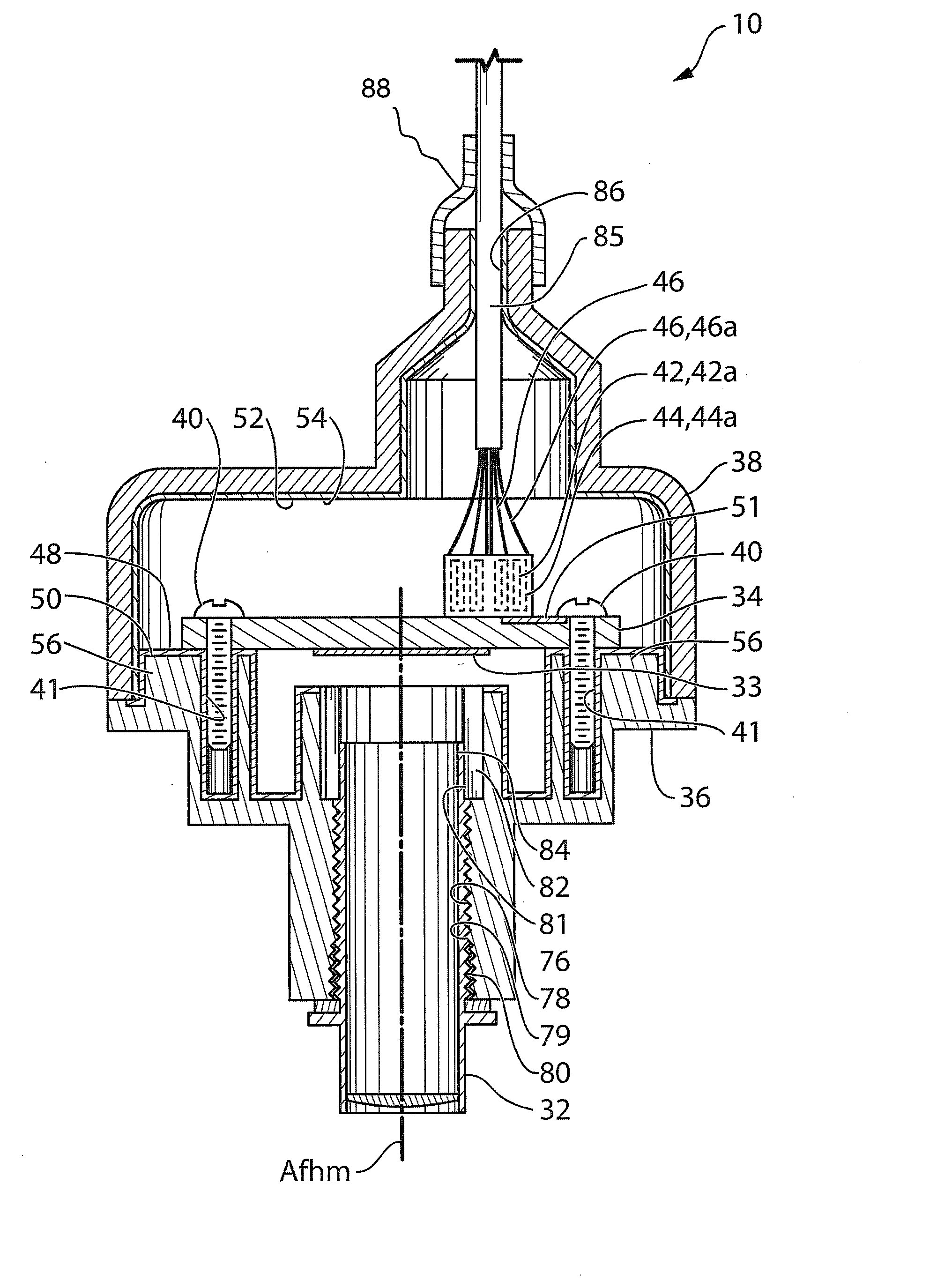
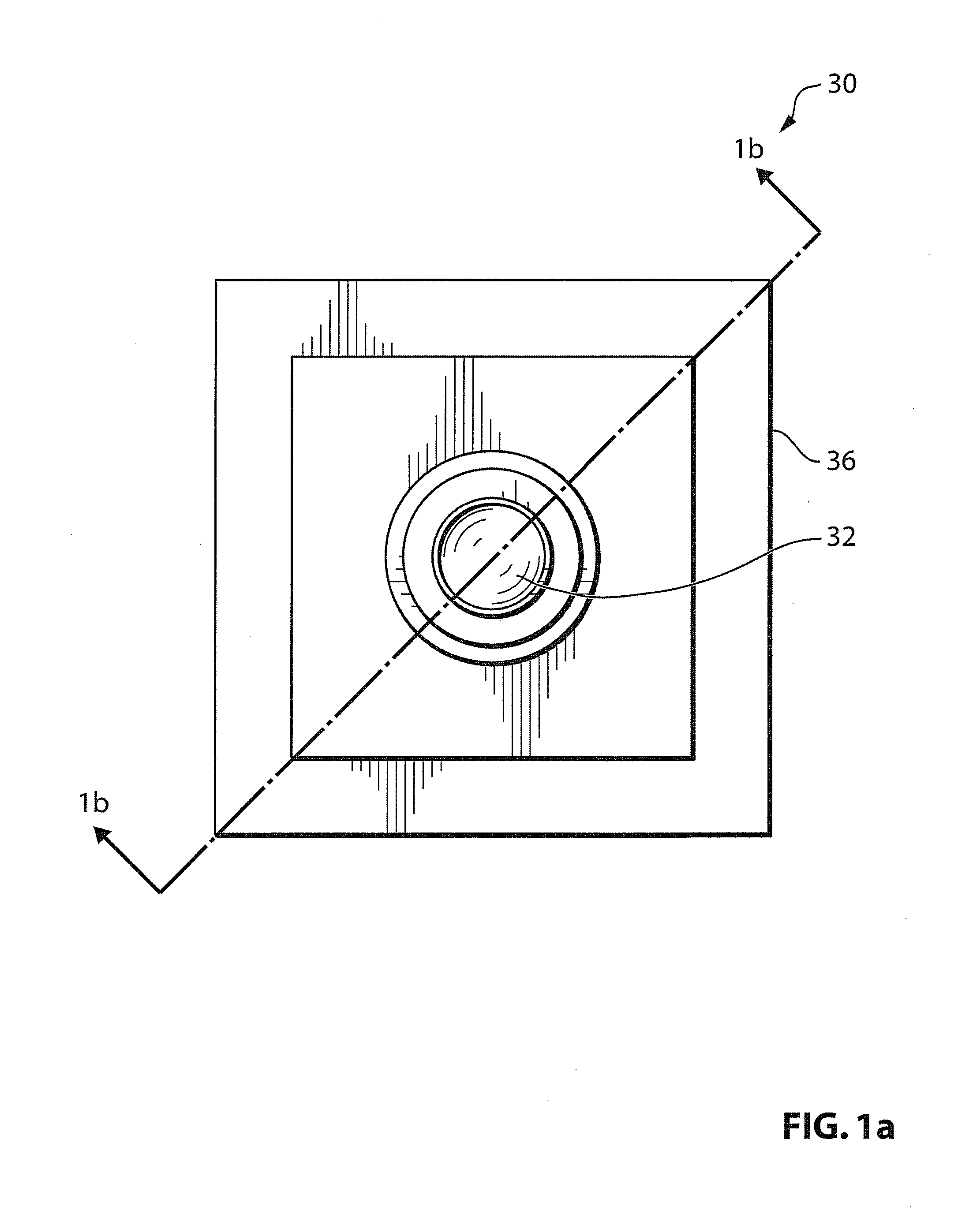
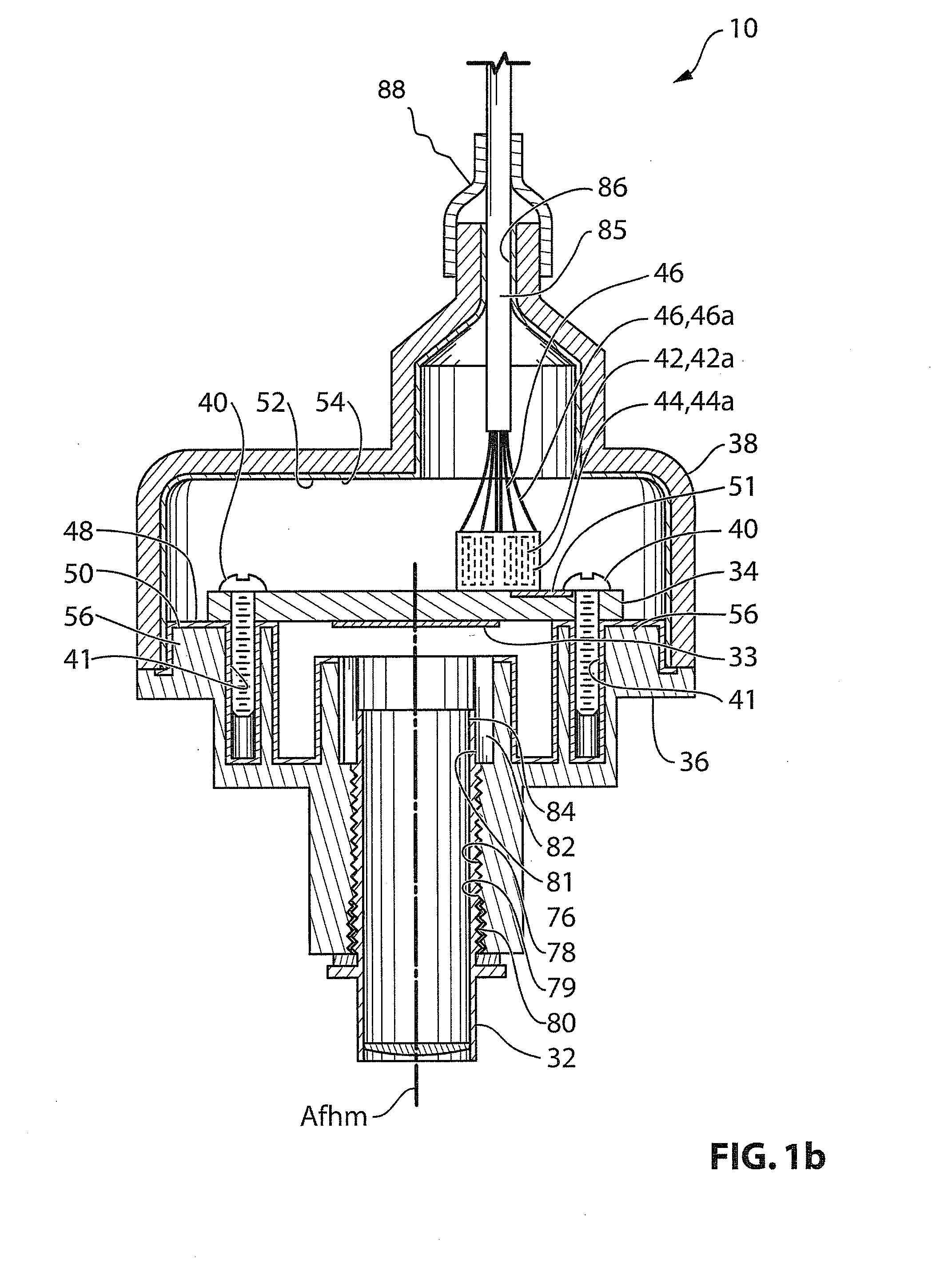
[0023]Reference is made to FIG. 1a, which shows a camera 30 for use in a vehicle, and in particular for use as a rearview camera in a vehicle, in accordance with an embodiment of the present invention. In one aspect, the camera 30 is configured to provide grounding protection and electromagnetic compatibility (EMC) protection simply and without adding to the complexity of the assembly. Referring to FIG. 1b, which is a sectional view of the camera 30, the camera 30 includes a lens 32, an imaging element 33, a circuit board 34, a front housing member 36 and a rear housing member 38.

[0024]Note that the terms ‘front’ and ‘rear’ as used in the present document refer to the front of the camera 30 (ie. the portion of the camera where the lens member is located), and the rear of the camera 30 (ie. the portion of the camera 30 opposite the front of the camera 30). When the camera 30 is used in a rearview application in a vehicle, the front of the camera 30 thus faces rearwardly relative to t...


PUM


Abstract

In one aspect, the invention is directed to a camera for mounting on a vehicle, wherein the camera housing made up of two housing members, with a conductive coating on the interior of each of the housing members. The two housing members mate together using an interference fit, to provide a greater assurance that they are electrically connected to each other. One of the housing members is connected to ground. In another aspect, the invention provides a camera module that has a housing and a wire harness or wire or lead that is electrically connected to circuitry of the camera and that extends through the camera housing for electrical connection to a vehicle wire harness or the like. The wire or lead extends through a portion of the housing with the housing disposed at the wire prior to connection of the wire to the circuitry of the camera. The electrical connection of the wire to the camera circuitry is made as the housing is assembled. The joint at where the wire extends outward from the housing portion is sealed, such as via shrink wrapping or the like.

Description

[0001]This application claims the benefits of U.S. Provisional Application No. 61 / 105,852, filed Oct. 16, 2008 and U.S. Provisional Application No. 61 / 148,568, filed Jan. 30, 2009.FIELD OF THE INVENTION[0002]The present invention relates to a camera for use in vehicles, and more particularly rearview cameras for use in vehicles.BACKGROUND OF THE INVENTION[0003]A typical camera for mounting on a vehicle has a lens member, an imaging element, a circuit board and housing members that connect together. It is generally desirable to reduce the cost of manufacture of such cameras and to improve their reliability.[0004]As an example, some cameras may use an epoxy to mount the lens member to the front housing member. However, the epoxy that is used may be susceptible to softening under high temperature, at which point the lens member becomes vulnerable to being moved out of focus with the imaging element. It would be desirable to reduce the vulnerability of the lens member to movement under ...

Claims


Application Information

Patent Timeline
Patent Type & Authority Applications(United States)
IPC IPC(8): H04N5/225
CPCB60R1/00B60R11/04H04N5/2252H04N23/51H04N23/57H04N23/54H04N23/55B60R2300/8006B60R2300/8026
Inventor BYRNE, STEVEN V.STICKLER, BENRIEDEN, RICHARDSESTI, MATTHEW C.BRASIER, BRIAN DEAN
Owner MAGNA ELECTRONICS
Why Eureka
Try Eureka