Supercharge Your Innovation With Domain-Expert AI Agents!

Scanning exposure method

a scanning exposure and exposure parameter technology, applied in the field of scanning exposure method, can solve the problems of ineffective determination of exposure parameters, differences in overlay shift relationship, and higher cos

Inactive Publication Date: 2010-04-22
NAN YA TECH
View PDF2 Cites 0 Cited by
  • Summary
  • Abstract
  • Description
  • Claims
  • Application Information

AI Technical Summary

Benefits of technology

The invention provides a method for scanning exposure where a mask and substrate move relative to each other at different speeds during a one-shot exposure. This results in an exposed shot area that is the expected size. The method also includes determining a uniform relative velocity between the mask and substrate based on historical information and measured data from a previous exposure. This allows for precise control over the exposure process.

Problems solved by technology

However, due to a real structural difference between the pre-layer of the test wafer and multi pre-layers of the product wafer, there are slight differences in the overlay shift relationship of the pre-layer and current layer of the test wafer and the product wafer, even if the test wafer and the product wafer are exposed by using the same exposure parameters.
Therefore, the exposure parameters can not effectively be determined by merely only using the measured data of the test wafer.
In addition, running test wafers before production ramp-up to obtain the exposure parameters result in higher costs due to the requirement of using acid solvents to rework the exposed test wafer.
Moreover, increased running of test wafers decreases lifespan of the exposure tool.
Therefore, production yield is decreased and manufacturing costs are increased.

Method used


Image

  • Scanning exposure method
  • Scanning exposure method
  • Scanning exposure method

Examples


Embodiment Construction

[0017]The following description is of the best-contemplated mode of carrying out the invention. This description is made for the purpose of illustrating the general principles of the invention and should not be taken in a limiting sense. The scope of the invention is best determined by reference to the appended claims.

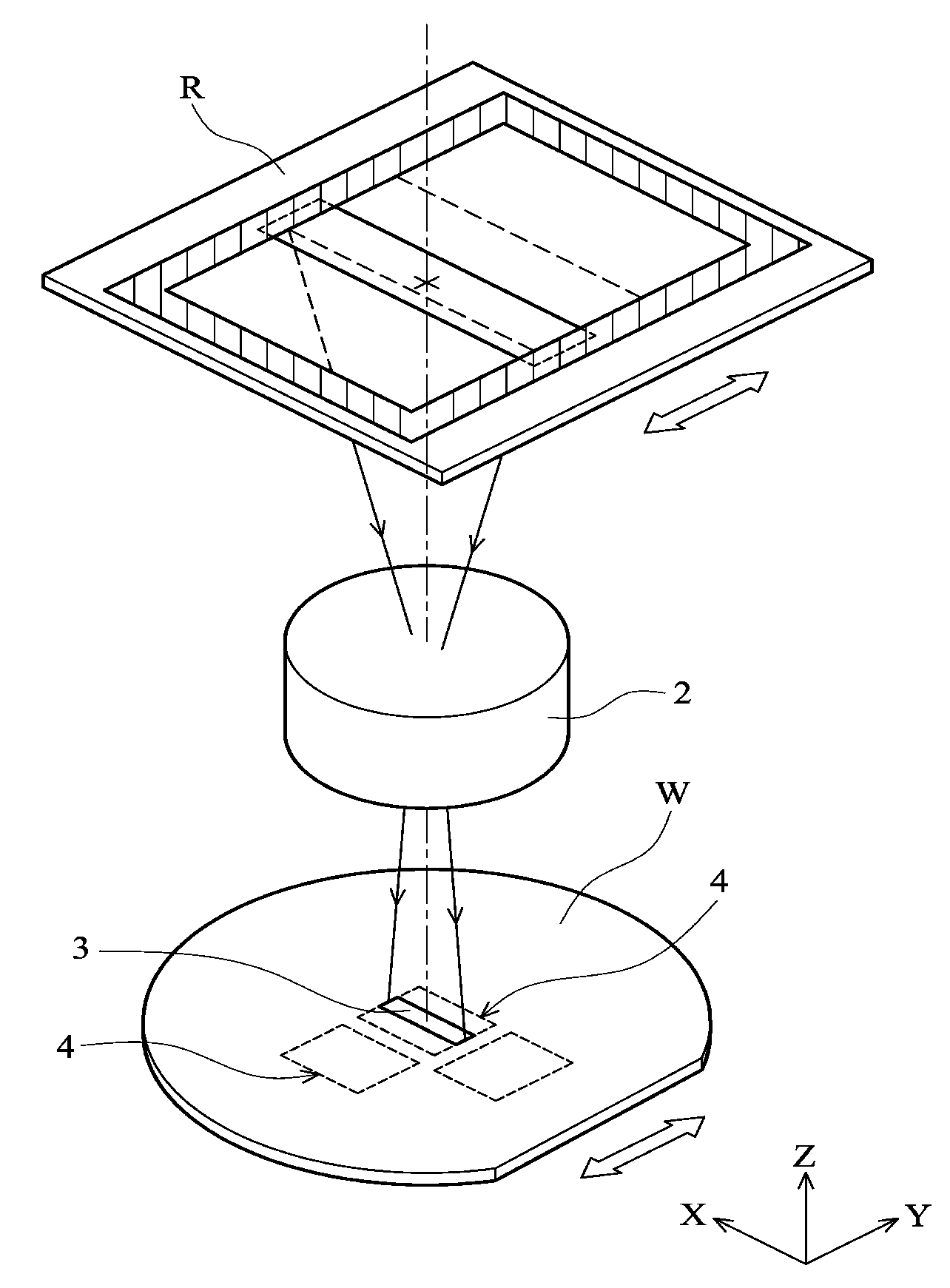
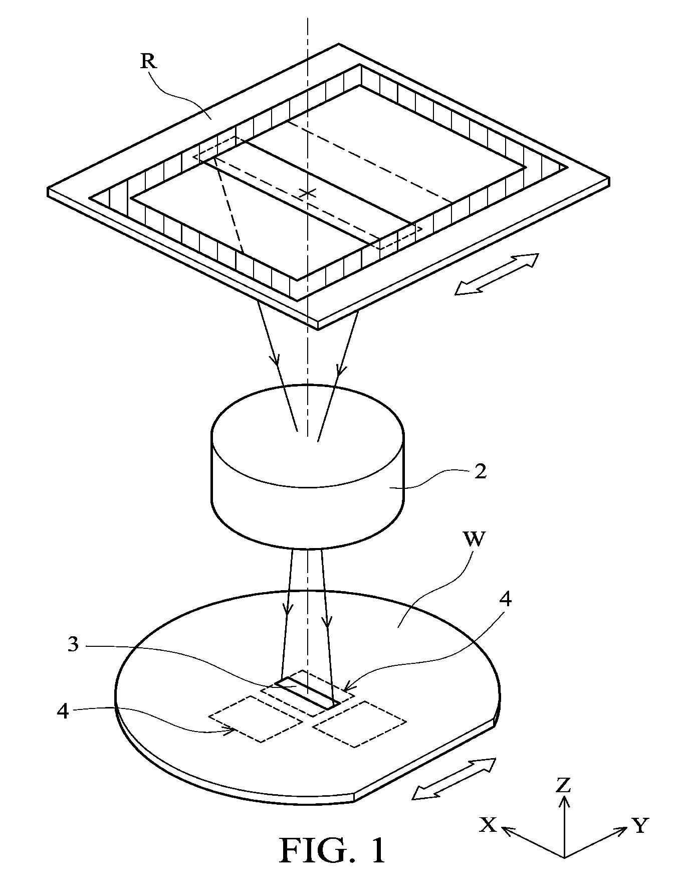
[0018]A scanning exposure method of the present invention is provided. Preferred exposure parameters of an exposure tool can be determined by using exposure tool historical information of a previously processed substrate, and measured data of the exposed substrate. The obtained exposure parameters can be used for offsetting (or compensating) fabrication process degree shifts or variations of the exposure tool. Therefore, a subsequent wafer exposure by the exposure tool can have an exposed shot area of an expected size thereon. In addition, the overlay quality between a current photoresist layer and a pre-layer is improved. The substrate may be a wafer, a display substr...


PUM


Abstract

A scanning exposure method is provided. A mask and a substrate are oppositely moved along a direction. The mask and the substrate are moved in at least two different uniform relative velocities during a one shot exposure, thus producing an exposed shot area of an expected size on the substrate.

Description

CROSS REFERENCE TO RELATED APPLICATIONS[0001]This Application claims priority of Taiwan Patent Application No. 97139881, filed on Oct. 17, 2008, the entirety of which is incorporated by reference herein.BACKGROUND OF THE INVENTION[0002]1. Field of the Invention[0003]The present invention relates to a lithography method, and in particular relates to a scanning exposure method.[0004]2. Description of the Related Art[0005]Continuing advances in semiconductor manufacturing processes have resulted in semiconductor devices with precision features and / or higher degrees of integration manufactured by using higher level process control technologies. Therefore, for the lithography process, the overlay quality between semiconductor layers is important due to the scaling down of critical dimensions (CD) of the semiconductor layers.[0006]For semiconductor wafer manufacturing, to obtain appropriate exposure parameters of an exposure tool to manufacture products, a test wafer is usually used first...

Claims


Application Information

Patent Timeline
Patent Type & Authority Applications(United States)
IPC IPC(8): G03B27/32
CPCG03F7/70358
Inventor SHIH, CHIANG-LINHUANG, CHUN-YEN
Owner NAN YA TECH
Features
  • R&D
  • Intellectual Property
  • Life Sciences
  • Materials
  • Tech Scout
  • Unparalleled Data Quality
  • Higher Quality Content
  • 60% Fewer Hallucinations
Learn More