
Method and apparatus for allocating wireless resource and wireless network system

Inactive Publication Date: 2010-04-22
ELECTRONICS & TELECOMM RES INST
View PDF14 Cites 4 Cited by
  • Summary
  • Abstract
  • Description
  • Claims
  • Application Information

AI Technical Summary

Benefits of technology

[0008]Accordingly, in one aspect, there is provided a wireless resource allocation apparatus and method which makes service intervals more uniform during medium access slot (MAS) allocation to satisfy a traffic delay requirement and thereby improves required quality of service (QoS).
[0009]Also, there is provided a wireless resource allocation apparatus and method which increases distribution rate of MAS for minimizing idle MAS and thereby improves efficiency of resource distribution.
[0011]The designating of the reference location may designate the reference location such that an interval between the divided zones to which the medium access slots are to be allocated is minimized.
[0014]The MAS allocating unit may designate the reference location based on the calculated number of medium access slots such that an interval between the divided zones to which the medium access slots are to be allocated is minimized.
[0018]The MAC hierarchy control unit may designate the reference location based on the calculated number of medium access slots such that an interval between the divided zones to which the medium access slots are to be allocated is minimized.

Problems solved by technology

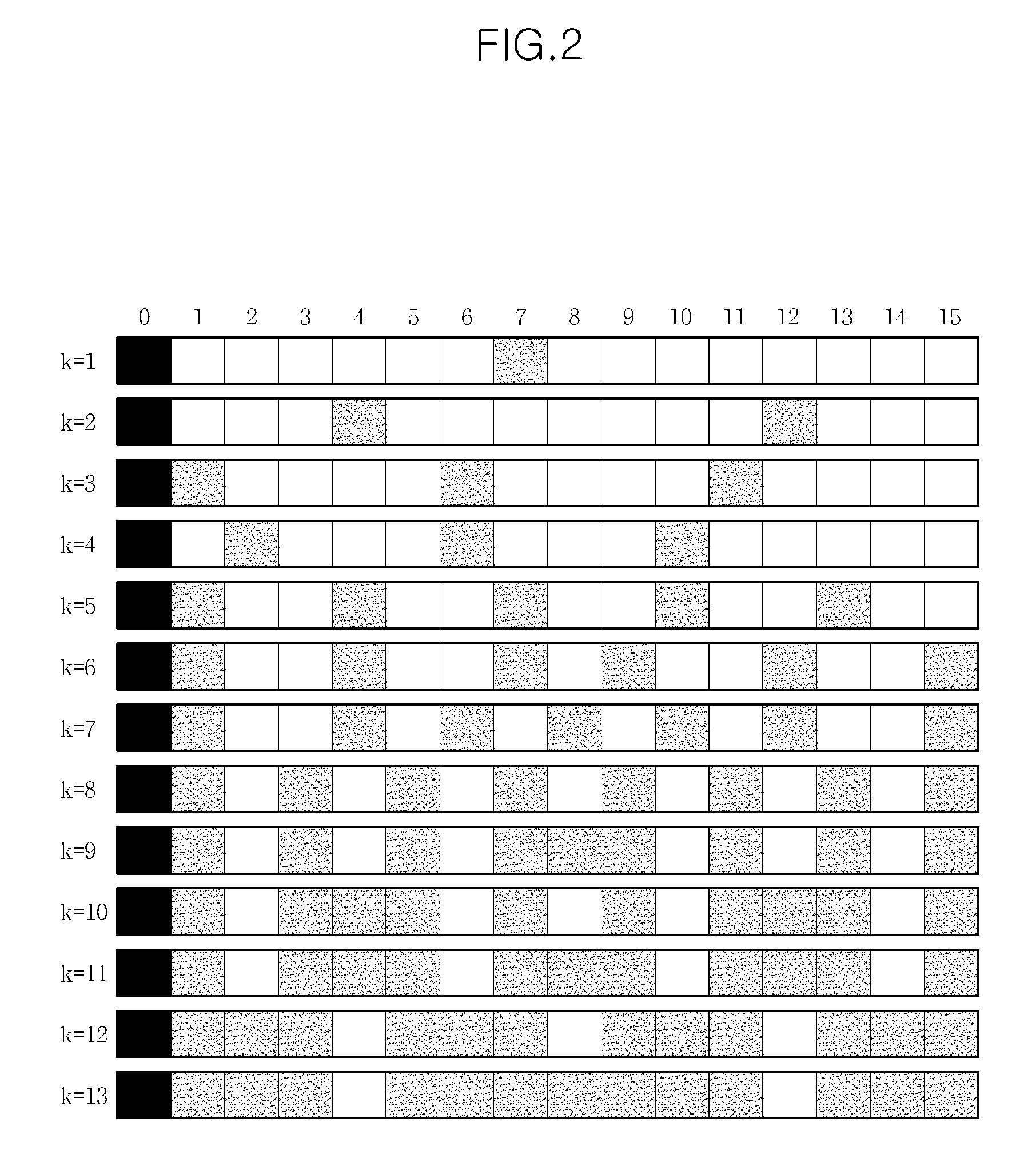
However, the SIMA scheme has a drawback in that service intervals may not be uniform during MAS allocation depending on the number of iso-zones k. Furthermore, even if the superframe contains sufficient idle MAS for satisfying QoS required by a higher TSPEC, since the iso-zone based SIMA scheme cannot allocate further MAS, then there are limits to the efficient resource allocation management that can be obtained.

Method used


Image

  • Method and apparatus for allocating wireless resource and wireless network system
  • Method and apparatus for allocating wireless resource and wireless network system
  • Method and apparatus for allocating wireless resource and wireless network system

Examples


Embodiment Construction

[0027]The following detailed description is provided to assist the reader in gaining a comprehensive understanding of the methods, apparatuses and / or systems described herein. Various changes, modifications, and equivalents of the systems, apparatuses and / or methods described herein will suggest themselves to those of ordinary skill in the art. Descriptions of well-known functions and structures are omitted to enhance clarity and conciseness.

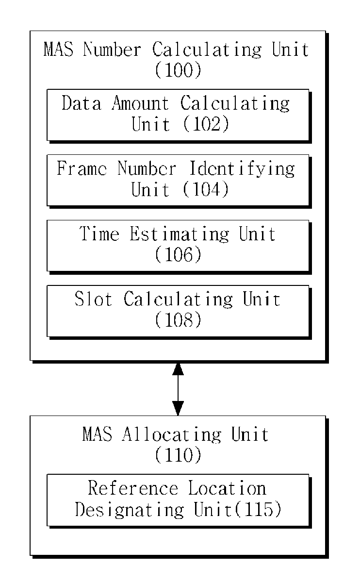
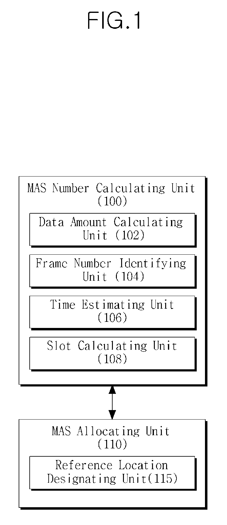
[0028]FIG. 1 is a block diagram illustrating an exemplary wireless resource allocation apparatus. The apparatus includes a medium access slot (MAS) number calculating unit 100 and a medium access slot (MAS) allocating unit 110.

[0029]The MAS number calculating unit 100 calculates the number of medium access slots (MAS) allocated to one of a plurality of divided zones of a superframe.

[0030]The superframe is composed of time slots, i.e., the medium access slots (MASs), and is divided into a beacon zone and a data zone. MASs belonging to the beacon ...


PUM


Abstract

A wireless resource allocation apparatus and method which maintain quality of service (QoS) in a wireless communication network are provided. The wireless resource allocation method includes calculating the number of medium access slots (MAS) to be allocated to at least one of a plurality of divided zones of at least one superframe, designating a reference location for MAS allocation to divided zones out of the plurality of divided zones of the superframe based on the calculated number of medium access slots, and allocating the medium access slots to the divided zones based on the designated reference location. Accordingly, more uniform service intervals can be supported, and thus efficient MAS resource allocation can be performed to satisfy media access control (MAC) based QoS requirements.

Description

CROSS REFERENCE TO RELATED APPLICATION[0001]This application claims the benefit under 35 U.S.C. § 119(a) of Korean Patent Application No. 10-2008-103643, filed on Oct. 22, 2008, the disclosure of which is incorporated herein in its entirety by reference.BACKGROUND[0002]1. Field[0003]The following description relates to a network resource allocation technique, and more particularly, to a resource allocation apparatus and method which maintains quality of service (QoS) in a wireless communication network.[0004]2. Description of the Related Art[0005]WiMedia logical link control protocol (WLP) for a wireless network provides a service interval based medium access slot allocation (SIMA) technique for reliable quality of service (QoS) in a time division multiple access (TDMA)-based system employing distributed reservation protocol (DRP).[0006]SIMA technique uses a traffic specification (TSPEC) of an application to obtain the maximum allowable values of a service rate and a delay time and ...

Claims


Application Information

Patent Timeline
IPC IPC(8): H04L12/43
CPCH04W72/1236H04W72/0446H04W72/543
Inventor SUNG, JUNG-SIKHUH, JAE-DOO
Owner ELECTRONICS & TELECOMM RES INST
Learn More