Thermal imaging-based vehicle analysis

a vehicle analysis and thermal imaging technology, applied in the field of thermal imaging based analysis, can solve the problems of inability to detect errors, high labor intensity, and current approaches to evaluate vehicles, such as rail vehicles, and achieve the effects of accurate determination of presence or absence, reduced false detection, and increased comprehension and analysis

Active Publication Date: 2010-04-22
INT ELECTRONICS MACHINES
View PDF88 Cites 130 Cited by
  • Summary
  • Abstract
  • Description
  • Claims
  • Application Information

AI Technical Summary

Benefits of technology

[0011]In an illustrative implementation of an embodiment of the invention, infrared image data is acquired for rail vehicles in a classification yard. The images acquired are then subjected to sophisticated image analysis and this analysis used to accurately determine the presence or absence of the various flaws or faults described previously. Unlike prior approaches, embodiments of the invention: enable analysis of components of rail vehicles at very slow to moderate speeds (e.g., in a classification yard), enable the detection and classification of smaller temperature differences as faults, use pattern recognition processes to substantially reduce false positives / negatives, enable the detection of additional types of faults and differentiation between faults, do not require installation of sensing components on or in close proximity to the rail (and therefore is not adversely impacted by vibrations), enable the fusion of lower resolution infrared image data with higher resolution visible image data to increase comprehension and analysis of the data, and / or the like.

Problems solved by technology

In general, the inventors recognize that current approaches for evaluating vehicles, such as rail vehicles, are error prone.
As a result, very high threshold temperatures are used as a work around to prevent excessive false positives, resulting in some errors not being detected.
However, even these high threshold temperatures do not prevent some false positives, resulting in costly disruptions to rail travel.

Method used


Image

  • Thermal imaging-based vehicle analysis
  • Thermal imaging-based vehicle analysis
  • Thermal imaging-based vehicle analysis

Examples


Embodiment Construction

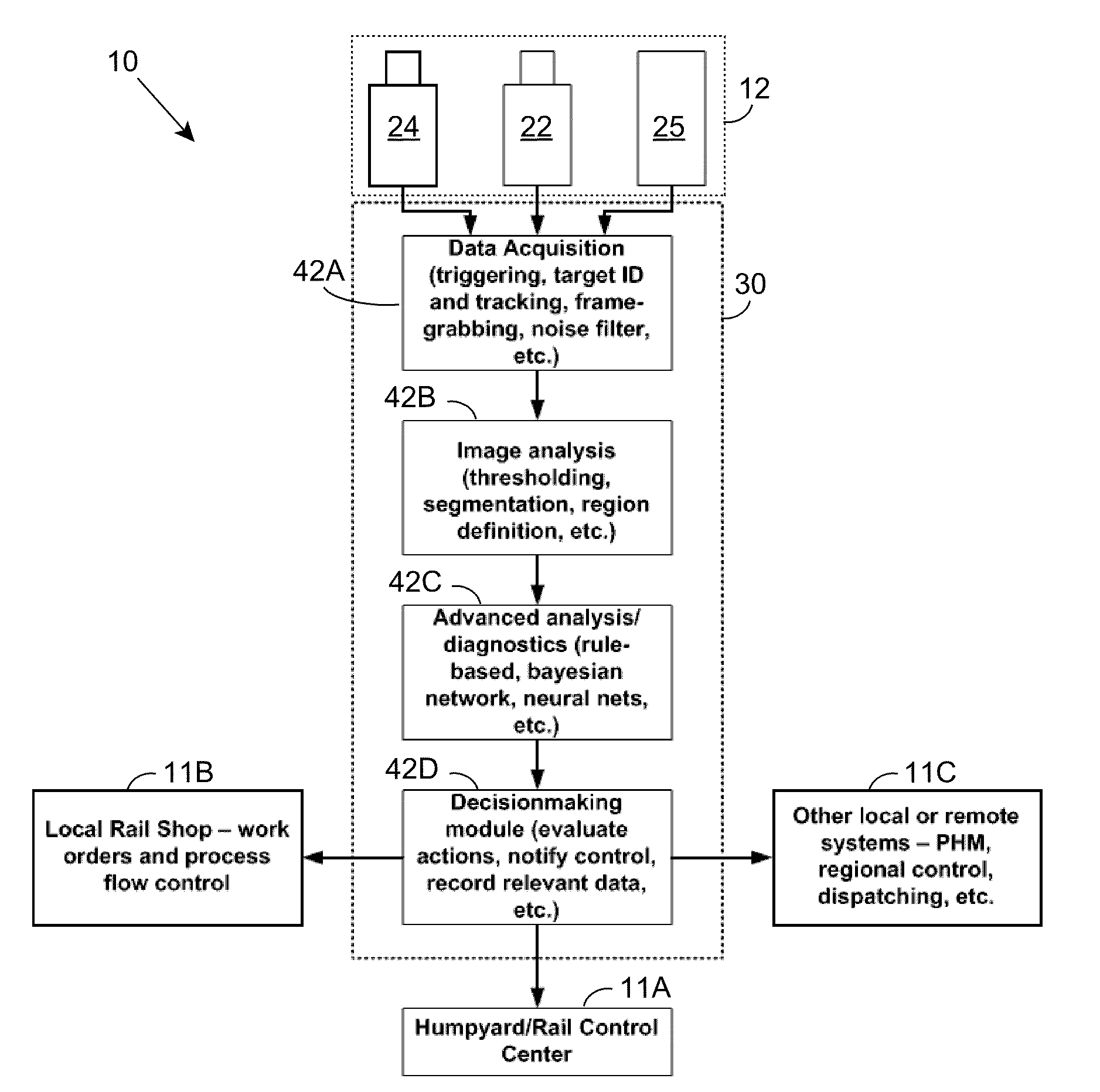
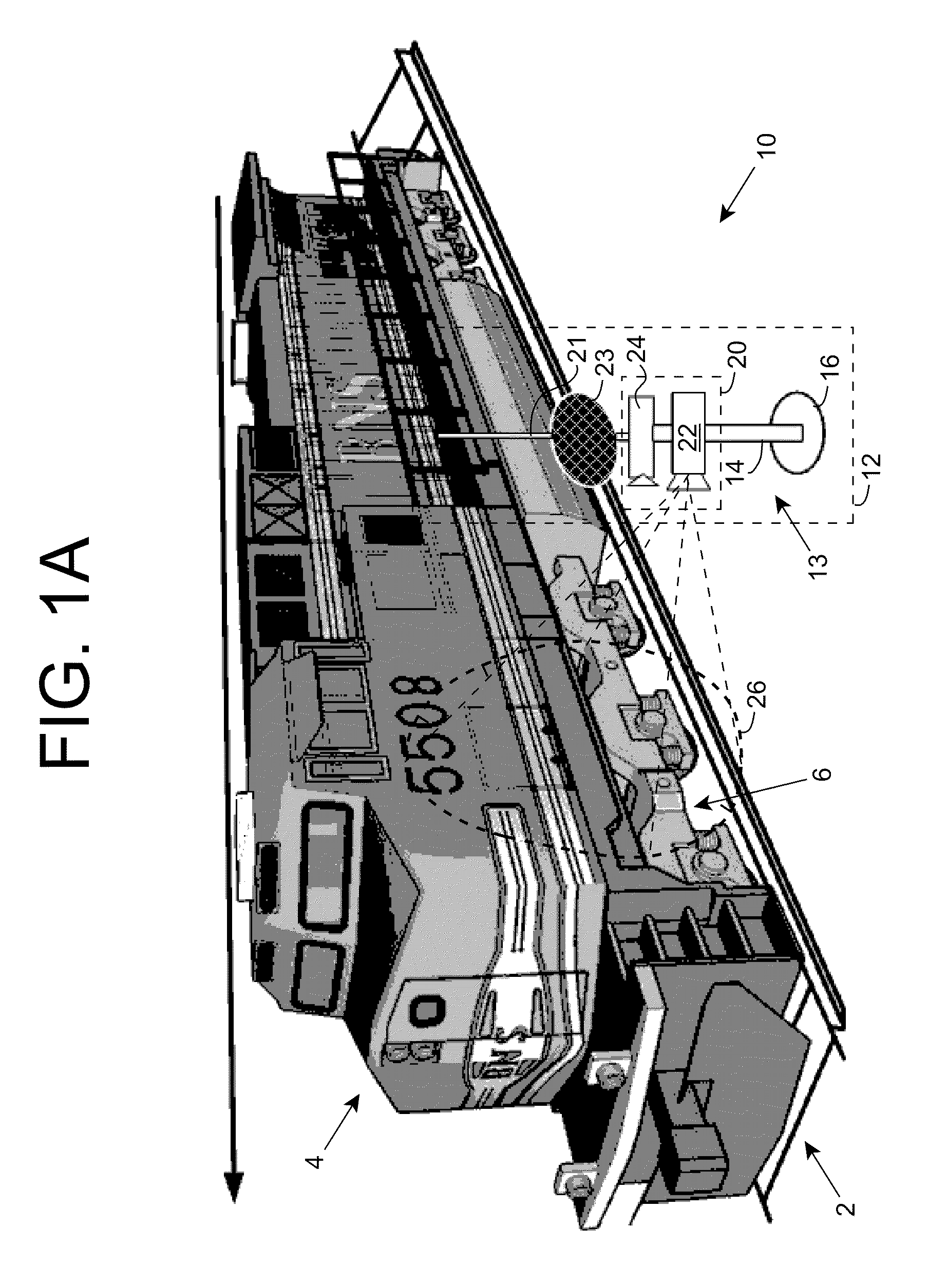
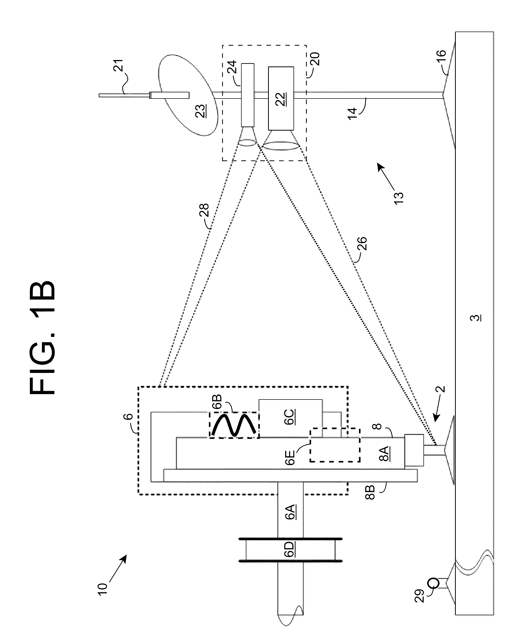
[0033]As indicated above, aspects of the invention provide a solution for analyzing a vehicle using multi-dimensional infrared image data acquired for the vehicle. A component of the vehicle can be identified within the infrared image data, and the infrared image data for the component can be analyzed to determine whether any condition(s) are present on the vehicle. One or more actions can be initiated in response to a determination that a particular condition is present. Additionally, visible image data can be used to supplement the infrared image data. Still further, infrared image data for similar components imaged concurrently with the component can be used to identify whether any condition(s) are present on the vehicle. Unlike prior art approaches in the rail industry, the analysis can be performed on rail vehicles within a classification yard. As used herein, unless otherwise noted, the term “set” means one or more (i.e., at least one) and the phrase “any solution” means any n...


PUM


Abstract

Analysis of a vehicle is performed using multi-dimensional infrared image data acquired for the vehicle. A component of the vehicle can be identified within the infrared image data, and the infrared image data for the component can be analyzed to determine whether any condition(s) are present on the vehicle. One or more actions can be initiated in response to a determination that a particular condition is present. Additionally, visible image data can be used to supplement the infrared image data. Still further, infrared image data for similar components imaged concurrently with the component can be used to identify whether any condition(s) are present on the vehicle. Unlike prior art approaches in the rail industry, the analysis can be performed on rail vehicles within a classification yard.

Description

REFERENCE TO PRIOR APPLICATIONS[0001]The current application claims the benefit of co-pending U.S. Provisional Application No. 61 / 193,012, titled “Infrared-based inspection of railway components”, which was filed on 22 Oct. 2008, and which is hereby incorporated by reference.[0002]Aspects of the current application are also related to U.S. Utility application Ser. No. 11 / 748,714, titled“Vehicle evaluation using infrared data”, which was filed on 15 May 2007, and which is hereby incorporated by reference.TECHNICAL FIELD[0003]The disclosure relates generally to thermal-imaging based analysis, and more particularly, to the analysis of various components of a vehicle using thermal image data.BACKGROUND ART[0004]Effective detection of one or more flaws in vehicles, such as rolling stock components in the rail industry, is highly desirable. For example, detection of flaws or problems with the wheels, brake components (including drums, discs, etc.), electronic brake control system, air con...

Claims


Application Information

Patent Timeline
Patent Type & Authority Applications(United States)
IPC IPC(8): G01M17/08G06K9/46G06F19/00G06V10/143H01L31/00
CPCG01M17/013G01M17/08G01N21/88G01N25/72G01N2021/1765G06T2207/30108G01T1/00G06K9/2018G06T7/0004G06T2207/10048G01N2033/0085B61L1/20G06V10/143B61L27/57
Inventor MIAN, ZAHID F.MULLANEY, JEREMY C.GLASSER, NICHOLAS
Owner INT ELECTRONICS MACHINES
Why Eureka
Try Eureka