Dust collector for duster

a technology for dust collectors and dusters, applied in the direction of cleaning filter means, vacuum cleaners, domestic applications, etc., can solve the problems of dust scattering, polluting the surrounding environment, harming neighbors, etc., to prevent dusters and surroundings from being polluted, remove dust efficiently, and remove dust on the bristles of dusters.

Inactive Publication Date: 2010-04-29
KIM HAI KWANG +1
View PDF7 Cites 9 Cited by
  • Summary
  • Abstract
  • Description
  • Claims
  • Application Information

AI Technical Summary

Benefits of technology

[0019]With the dust collector for a duster according to invention, it is possible to remove dust on bristles of a duster easily and efficiently.
[0020]In particular, since it is easy to remove dust attached on the bristles of a duster inside of a house, the problem can be avoided, arising in taking off dust on a duster outside the house to annoy neighbors.
[0021]Since, by means of powerful suction of the dust collector, the dust taken off a duster is collected directly in the filter, it is possible to remove dust efficiently, and possible to prevent dusters and surroundings from being polluted again if the dust flies in all directions.
[0022]Also, since numerous germs, ticks, etc., included in the dust are killed in addition to removal of the dust according to the invention, the inventive dust collector can advantageously prevent atopic dermatitis, asthma, nasal inflammation, etc. caused thereby.

Problems solved by technology

However, such a method of shaking or washing a duster has the following problems.
When the duster is shaken outside of a house in the air, the dust scatters in all directions to pollute the surrounding environment and to do harm to neighbors, etc.
Accordingly, it is not an appropriate method of removing the dust absorbed on the duster several times while using it.

Method used


Image

  • Dust collector for duster
  • Dust collector for duster
  • Dust collector for duster

Examples


Embodiment Construction

[0032]Hereinafter, preferred embodiments of a dust collector for a duster according to the invention will be described in detail with reference to the accompanying drawings.

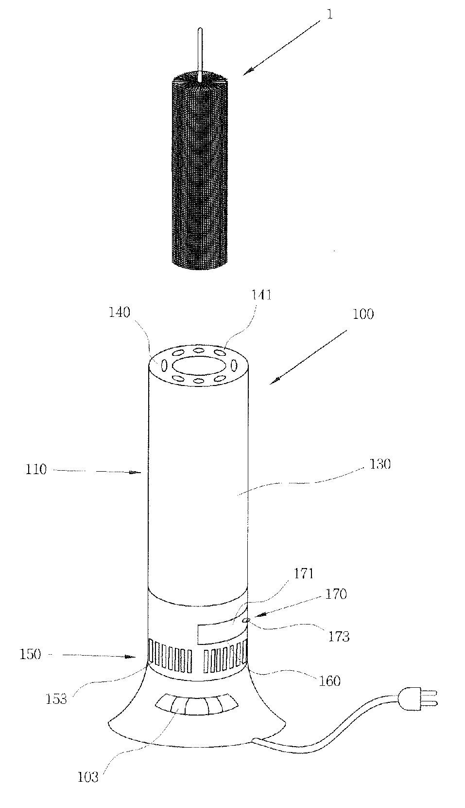
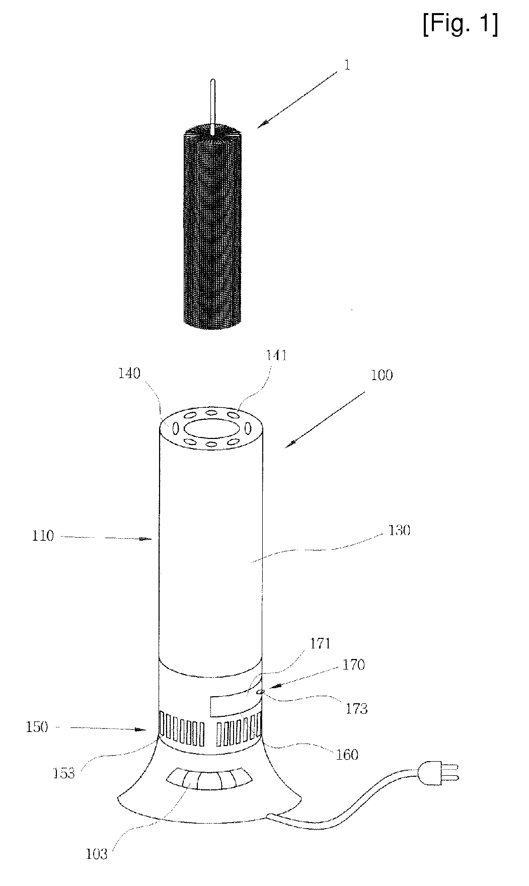
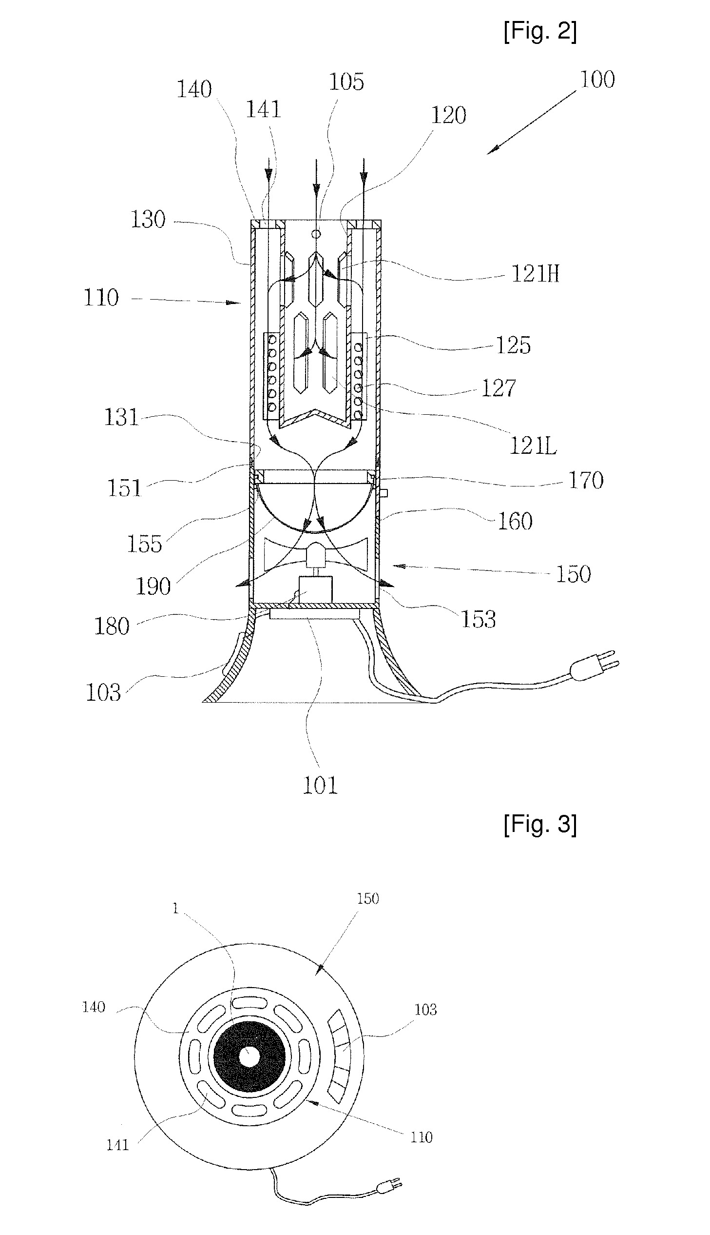
[0033]In the drawings, FIG. 1 is a perspective view showing a dust collector for a duster according to one embodiment of the invention. FIG. 2 is a profile of the dust collector for a duster shown in FIG. 1 and FIG. 3 is a top view of the dust collector for a duster shown in FIG. 1. FIG. 4 is a cross section of the dust collector for a duster shown in FIG. 1 and FIG. 5 is an exploded and perspective view of a filter holding unit shown in FIG. 2. FIG. 6 is a lateral view of a filter holding unit shown in FIG. 5 and FIG. 7, is a cross section of a filter holding unit shown in FIG. 6. FIG. 8 is a profile of a dust collector for a duster further having an ultraviolet lamp according to another embodiment of the invention.

[0034]As shown in FIGS. 1 to 3, a dust collector 100 for a duster according to the invention compr...


PUM


Abstract

The invention concerns a dust collector for a duster, and provides a dust collector for a duster for sucking and removing dust on the bristle of a duster. The dust collector for a duster in order to achieve the aforementioned object of the invention is characterized in that it comprises: a case having one side of a dual pipe type of an inner pipe and an outer pipe and the other side provided with exhaust holes, and also having a structure of transferring dust taken off the duster placed inside of the inner pipe through openings provided on the inner pipe to a filter with air and then discharging only the air; a fan provided in the case for forcibly transferring the sucked air through the openings to the exhaust holes to discharge it; and a filter provided in an air transfer path in the case and for collecting the dust transferred with the air.

Description

TECHNICAL FIELD[0001]The present invention relates to a dust collector for a duster, and more particularly to a dust collector for a duster for sucking and then removing dust from the duster that absorbs dust by means of static electricity.BACKGROUND ART[0002]A duster using static electricity is a cleaning tool for generating static electricity easily to suck fine dust, which duster is widely used because the duster efficiently removes dust using static electricity. With the duster, the only thing a user has to do is to just wipe every dusty place to remove the dust, even if the dust is in a place where it is hard to remove it with a wet dust cloth, such as on electronic products or books using static electricity.[0003]Such a duster can be reused after removing the dust thereon when too much dust is absorbed thereon because of repeated use. The dust absorbed on the duster may be removed by shaking the duster in the air outside of a house or washing it. However, such a method of shak...

Claims


Application Information

Patent Timeline
Patent Type & Authority Applications(United States)
IPC IPC(8): A47L9/10
CPCA47L7/0057A47L7/02A47L5/12A47L7/00
Inventor KIM, HAI KWANGKIM, JEONG EUN
Owner KIM HAI KWANG
Why Eureka
Try Eureka