Controlling a liquid flow through heater

Inactive Publication Date: 2010-04-29
KONINKLIJKE PHILIPS ELECTRONICS NV
View PDF41 Cites 9 Cited by
  • Summary
  • Abstract
  • Description
  • Claims
  • Application Information

AI Technical Summary

Benefits of technology

[0016]In an embodiment, the temperature sense unit comprises a first temperature sensor to sense a first sensed temperature and a second temperature sensor to sense a second sensed temperature. The first and the second sensed temperatures being different ones of the sensed temperature of the wall of the channel, or the sensed temperature of the wall of the electric heater element, or the sensed temperature of the liquid when in the channel. The use of more than one sensor may improve the temperature behavior of the system. However, a drawback is that two sensors are required.
[0017]In an embodiment, the controller detects during the first phase when the first sensed temperature rises above a predetermined value, and starts the second phase at this instant. The controller stabilizes the second sensed temperature during the third

Problems solved by technology

Although, a closed loop feedback is present to control the power supplied to the second heater element in dependence on the sensed te

Method used


Image

  • Controlling a liquid flow through heater
  • Controlling a liquid flow through heater
  • Controlling a liquid flow through heater

Examples


Embodiment Construction

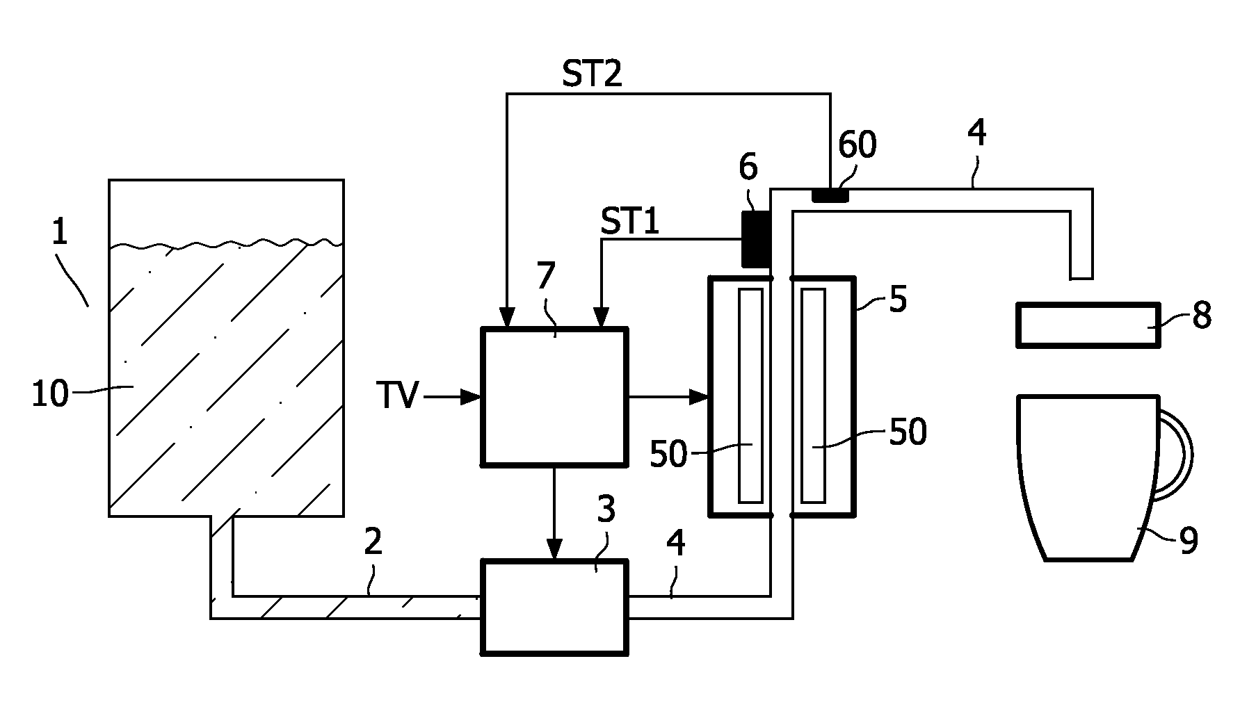
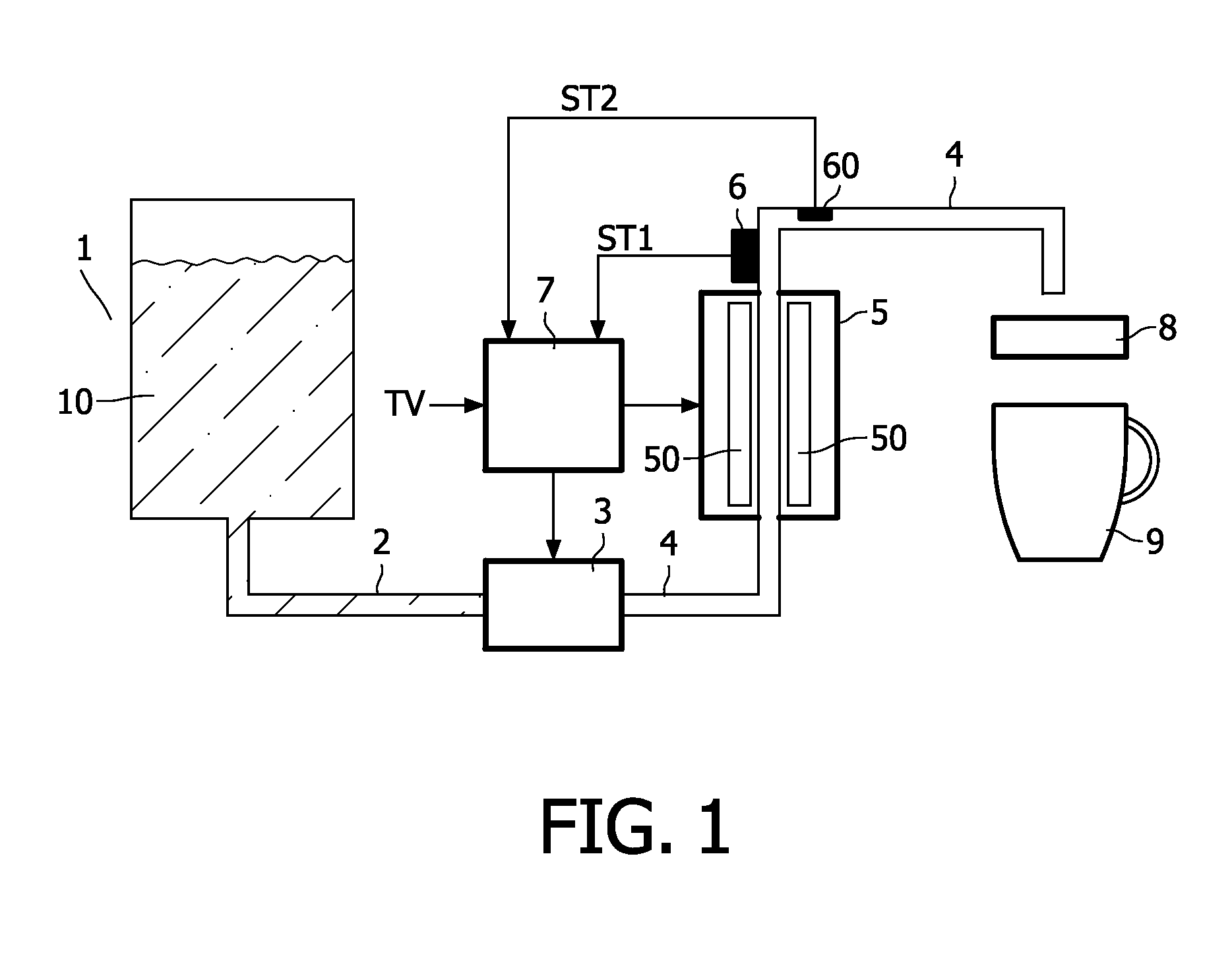
[0025]FIG. 1 shows schematically an embodiment of a beverage brewing machine with a flow through heater. The beverage brewing machine comprises a water reservoir 1 in which the liquid 10 to be heated is stored. Usually, in beverage brewing machines this liquid is water, but alternatively, the liquid may be milk.

[0026]In the embodiment shown in FIG. 1, a pump 3 pumps the water 10 from the water reservoir 1 into a cup 9. The water 10 enters the pump 3 via a channel or conduit 2 and is supplied by the pump to the channel 4. The pump 3 pumps the water through the channel 4 via a consumable pad 8 into the cup 9. Alternatively, instead of the pump 3 a valve may be used if the lowest level of the water 10 in the water reservoir 1 is higher than the highest fill level in the cup 9, such that the water 10 can fall from the reservoir 1 into the cup 9 without the need for a pump 3. For example, the consumable pad 8 may contain coffee or thee. Instead of the consumable pad 8 a user refillable h...


PUM


Abstract

A liquid flow through heater for heating a liquid (10) comprises a channel (4) and an electric heater element (50) for heating at least a portion of the channel (4). A temperature sense unit (6, 60) senses a temperature (ST1; ST1, ST2) indicative of the temperature of the liquid. A flow control means (3) controls a flow of the liquid (10) through the channel (4). A controller (7) controls in a first phase (PH1), (i) the electric heater element (50) to pre-heat at least the portion of the channel (4), and (ii) the flow control means (3) to obtain a rate of flow of the liquid (10) through the channel (4) which is zero or relatively small with respect to a rate of flow during a second and/or third phase. The controller (7) controls in the second phase (PH2) succeeding the first phase (PH1), (i) the electric heater element (50) to supply a predetermined heating power independent on the sensed temperature (ST1; ST1, ST2), and (ii) the flow control means (3) to obtain a flow of the liquid (10) through the channel (4), and in the third phase (PH3) succeeding the second phase (PH2), (i) the electric heater element (50) to supply a heating power (HP) in dependence on the sensed temperature (ST1; ST1, ST2) to substantially stabilize the sensed temperature (ST1; ST1, ST2) on a desired target value (TV), and (ii) the flow control means (3) to obtain a flow of the liquid (10) through the channel (4).

Description

FIELD OF THE INVENTION[0001]The invention relates to a liquid flow through heater for heating a liquid flowing through a channel, and a beverage brewing machine comprising such a liquid flow through heater.BACKGROUND OF THE INVENTION[0002]US2002 / 0051632A1 discloses a water flow heater with a first heater element for supplying a fixed power and a second controllable heater element. A temperature sensor senses the temperature of the heated water. A control unit controls the heat supply from the second heater element in dependence on a temperature detected by the temperature sensor. A pump generates a water flow-rate lying within a predetermined range through the channel. In an embodiment, when heated water is desired, first a preheating phase occurs wherein the control unit switches on both heater elements. After the desired preheating period, the pump is activated and the water starts flowing through the heater elements. During this phase a closed loop feedback is used: the control u...

Claims


Application Information

Patent Timeline
IPC IPC(8): A47J31/44G05D7/06G05D23/19
CPCA47J31/56A47J31/545
Inventor MULDER, BERNARDO ARNOLDUS
Owner KONINKLIJKE PHILIPS ELECTRONICS NV
Why Eureka
Try Eureka