Tube shield and a method for attaching such shield to a boiler tube

a technology of boiler tubes and shields, which is applied in the direction of water-tube boilers, steam boiler components, corrosion prevention, etc., can solve the problems of cumbersome assembly and difficulty in replacing individual shield halves

Inactive Publication Date: 2010-04-29
METSO POWER AB
View PDF13 Cites 14 Cited by
  • Summary
  • Abstract
  • Description
  • Claims
  • Application Information

AI Technical Summary

Benefits of technology

[0005]An object of the invention is to provide a boiler tube shield and a method for attaching such a tube shield to a boile

Problems solved by technology

This makes assembly cumbersome.
The design will also make it difficult to replace individual tube shield halves if more than one set of tube shield halves are mount

Method used


Image

  • Tube shield and a method for attaching such shield to a boiler tube
  • Tube shield and a method for attaching such shield to a boiler tube
  • Tube shield and a method for attaching such shield to a boiler tube

Examples


Embodiment Construction

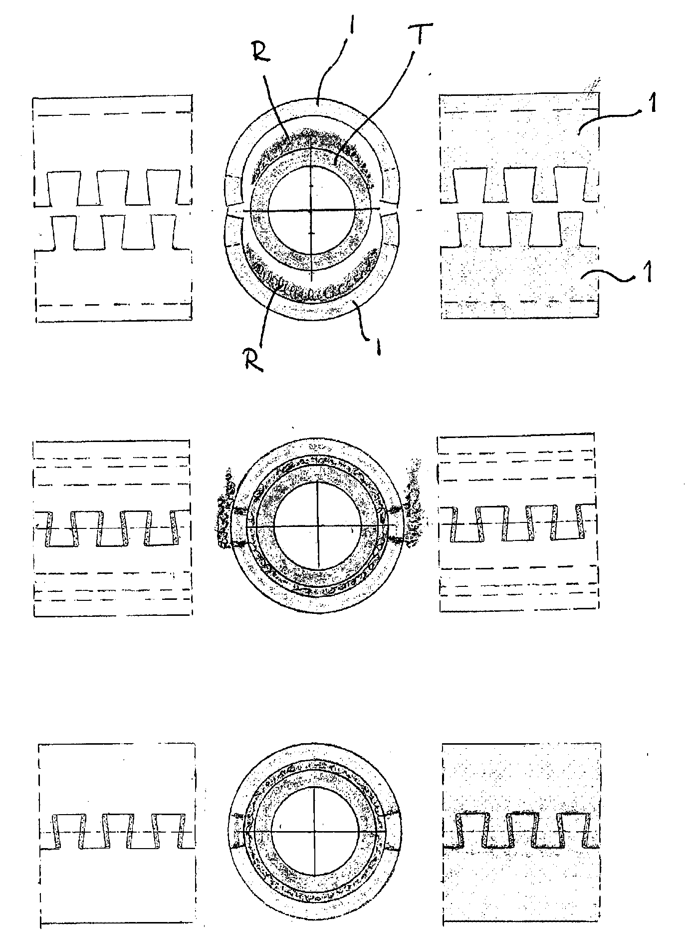
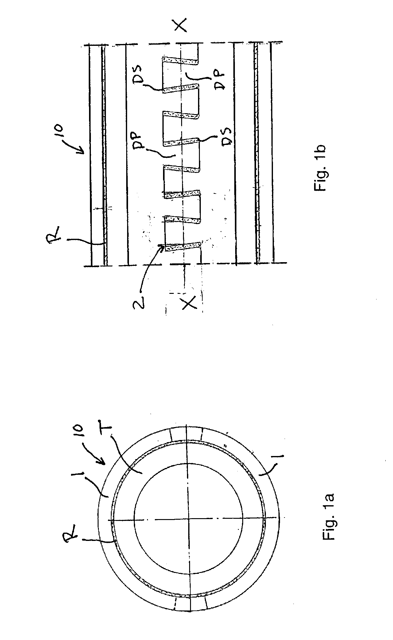
[0021]The boiler tube shield according to the present invention is comprised of a heat resistant material having excellent corrosion and erosion resistance, either a ceramic material or a high alloy steel material.

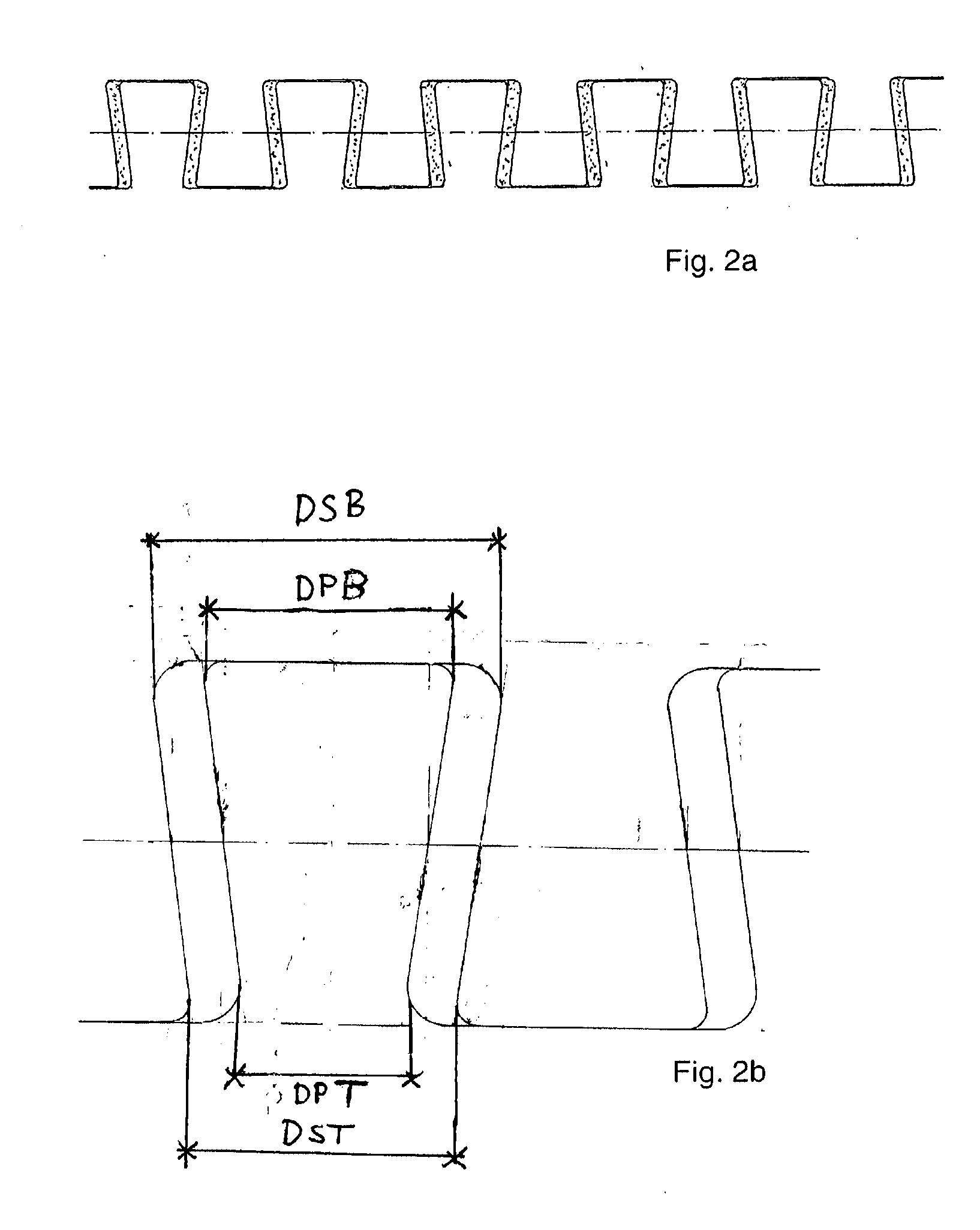
[0022]In case of ceramic material however, in order to minimize reduction in heat conductivity of that portion of the boiler tube at which the boiler tube shield is attached, it is preferable to select a ceramic material having excellent heat conductivity. As such a ceramic material having both corrosion resistance and heat conductivity, SiC may be recited by way of example. Ceramic materials in the tube shield are preferable for super heaters in waste boilers where tubes are subjected to a very aggressive environment and / or where durability is favored. The dove tail form according to the invention, in detail described in following parts, made in such tube shield in any such ceramic material could be made having a dove tail protrusions being at least 30 mm wide and with a ...


PUM

PropertyMeasurementUnit
Angleaaaaaaaaaa
Electrical resistanceaaaaaaaaaa
Circumferenceaaaaaaaaaa

Abstract

A tube shield has a cylindrical shape and adapted to be attached with refractory cement (R) around an outer peripheral surface of a boiler tube (T). The tube shield has at least two tube shield parts for surrounding the boiler tube (T). The shield parts has complimentary parting surfaces for defining a gap between abutting complimentary parting surfaces of adjacent shield parts when the shield parts are attached with refractory cement (R) around the boiler tube (T). Each shield part encloses 140-220° of the total circumference of the boiler tube (T). Each complimentary parting surface is configured in a dovetail form such that one shield part is locking into the other shield part with dovetail protrusions (DP) located in dovetail slots (DS) in the other shield part.

Description

TECHNICAL FIELD[0001]The present invention relates to a boiler tube shield in accordance with the preamble of claim 1 and a method for attaching such a shield to a boiler tube, in accordance with the preamble of claim 7.STATE IN THE ART[0002]U.S. Pat. No. 6,152,087 discloses a boiler tube shield having a cylindrical or semi-cylindrical shape and adapted to be attached around an outer peripheral face of a boiler tube with mortar. The boiler tube shield includes a plurality of ceramic bodies closely arranged along their parting planes, wherein the parting planes includes a restraining portion for restraining slippage of each of the ceramic bodies.[0003]U.S. Pat. No. 6,136,117 disclose a method of attaching a boiler tube shields having a cylindrical or semi-cylindrical shape around an outer peripheral face of a boiler tube with mortar. The boiler tube shields, are a plurality of ceramic bodies closely arranged along their parting planes, wherein the parting planes includes means for re...

Claims


Application Information

Patent Timeline
IPC IPC(8): F22B37/10F16L3/12B21D53/02
CPCF16L57/06Y10T29/4935Y10T29/49391F22B37/107
Inventor NORDH, LENNART
Owner METSO POWER AB
Why Eureka
Try Eureka