
Lighting device

a technology of light source and light source, which is applied in the direction of lighting and heating apparatus, instruments, and optical radiation measurement, etc., can solve the problems of adversely affecting the accuracy of the reading by the sensor(s), and inaccurate readings obtained from the sensor, so as to limit the variation in the amount of light sensed, reduce or minimize the effect of ligh

Active Publication Date: 2010-04-29
IDEAL IND LIGHTING LLC
View PDF38 Cites 117 Cited by
  • Summary
  • Abstract
  • Description
  • Claims
  • Application Information

AI Technical Summary

Benefits of technology

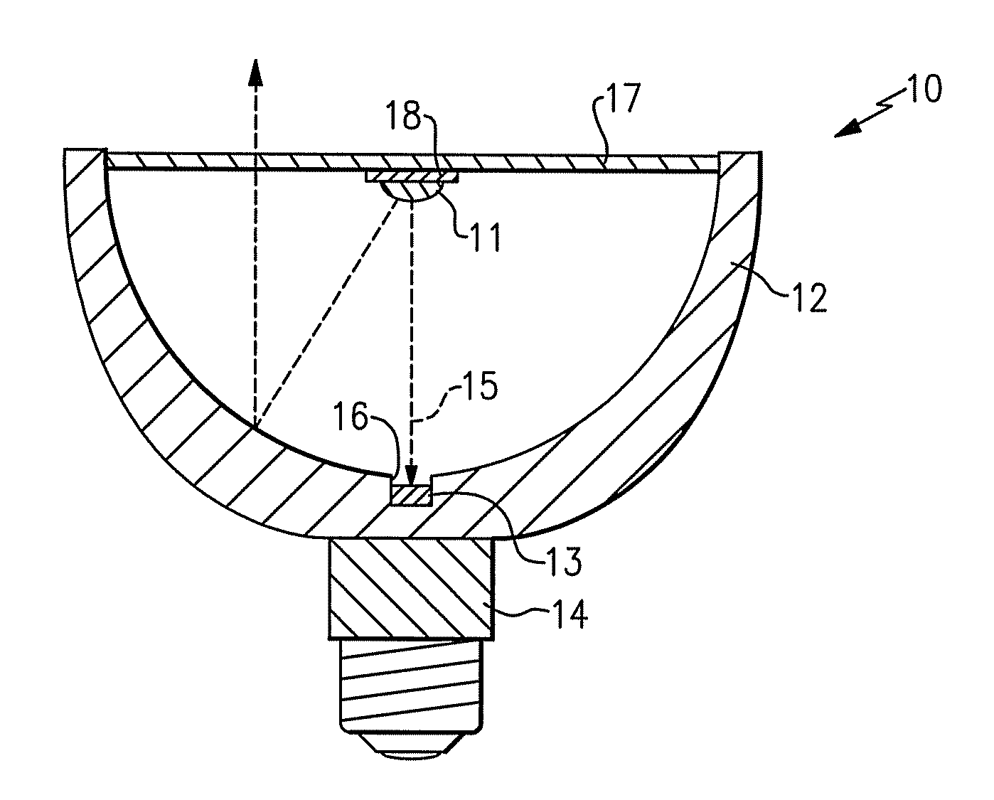
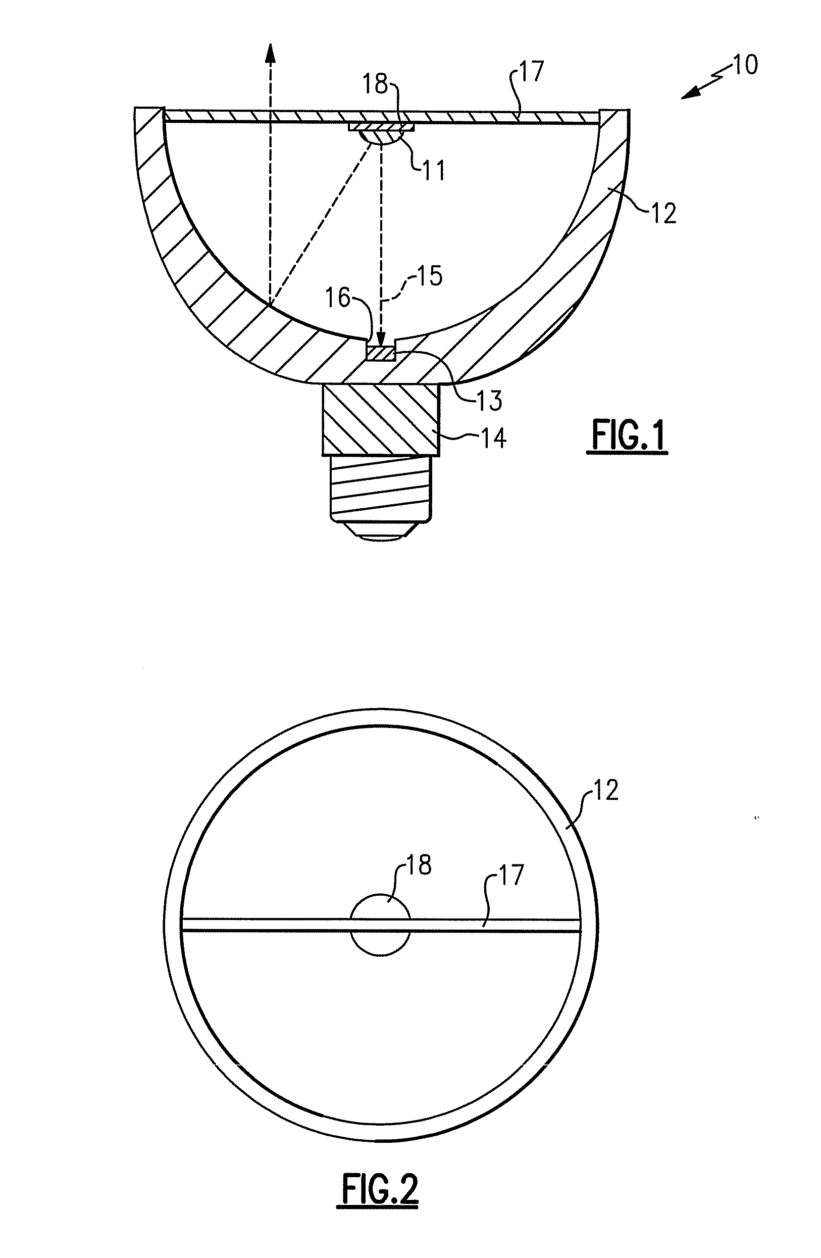
[0012]In many existing devices, sensors are mounted facing in the same direction that the light emitters output light. In accordance with the present inventive subject matter, there are provided back-reflecting and forward-reflecting lamps which comprise one or more sensors which directly view the light from the light emitter(s), e.g., which face toward the light emitter(s). As a result, the amplitude of the direct light is so great that it will swamp out any reflected or ambient light component. In some embodiments of the present inventive subject matter, as discussed below, the sensor is recessed in the reflector (or in one of the reflectors) to limit any variation in the amount of light sensed. In addition, in some embodiments, the sensor(s) is / are placed directly below the light emitter in the reflector, and a significant portion of the light that is output directly below the light emitter would otherwise be reflected back into the light emitter (if the sensor(s) according to the present inventive subject matter were not placed there), thereby reducing or minimizing the amount of light that is lost as a result of the placement of the sensor(s).

Problems solved by technology

In many cases, however, readings obtained from sensors are inaccurate for any of a variety of reasons.
For example, in some cases, ambient light is received by the sensor(s) in addition to light from the light emitter(s), and the intensity of the ambient light as received by the sensor(s), relative to the intensity of the light from the light emitter(s), is sufficiently large to adversely affect the accuracy of the reading by the sensor(s) to a significant degree.
In such cases, if an object (e.g., a white sheet of paper) is positioned close to the lighting device, the intensity of all color hues, including those to which the sensor(s) is sensitive will increase, thereby adversely affecting the accuracy of the reading by the sensor(s).
As a result, the amplitude of the direct light is so great that it will swamp out any reflected or ambient light component.

Method used


Image

  • Lighting device
  • Lighting device
  • Lighting device

Examples


Embodiment Construction

[0039]The present inventive subject matter now will be described more fully hereinafter with reference to the accompanying drawings, in which embodiments of the inventive subject matter are shown. However, this inventive subject matter should not be construed as limited to the embodiments set forth herein. Rather, these embodiments are provided so that this disclosure will be thorough and complete, and will fully convey the scope of the inventive subject matter to those skilled in the art. Like numbers refer to like elements throughout. As used herein the term “and / or” includes any and all combinations of one or more of the associated listed items.

[0040]The terminology used herein is for the purpose of describing particular embodiments only and is not intended to be limiting of the inventive subject matter. As used herein, the singular forms “a”, “an” and “the” are intended to include the plural forms as well, unless the context clearly indicates otherwise. It will be further unders...


PUM


Abstract

There is provided a lighting device, comprising at least one light emitter, at least one reflector and at least one sensor. The sensor is positioned within a region which receives direct light from the light emitter when the light emitter is emitting light. In some embodiments, the light emitter comprises one or more light emitting diode. In some embodiments, the sensor is positioned between the light emitter and a power supply. In some embodiments, the reflector comprises at least one opening, and light emitted by the light emitter passes through the opening to the sensor. In some embodiments, the sensor is sensitive to only some wavelengths of visible light. Some embodiments are back-reflecting lamps, and some are forward-reflecting lamps.

Description

CROSS-REFERENCE TO RELATED APPLICATION[0001]This application claims the benefit of U.S. Provisional Patent Application No. 61 / 108,133, filed Oct. 24, 2008, the entirety of which is incorporated herein by reference.FIELD OF THE INVENTIVE SUBJECT MATTER[0002]The present inventive subject matter relates to lighting devices. More particularly, the present inventive subject matter relates to lighting devices comprising a light emitter, a reflector and a sensor.BACKGROUND[0003]A large proportion (some estimates are as high as twenty-five percent) of the electricity generated in the United States each year goes to lighting. Accordingly, there is an ongoing need to provide lighting which is more energy-efficient. It is well known that incandescent light bulbs are very energy-inefficient light emitters—about ninety percent of the electricity they consume is released as heat rather than light. Fluorescent light bulbs are more efficient than incandescent light bulbs (by a factor of about 10) b...

Claims


Application Information

Patent Timeline
IPC IPC(8): G01J1/20
CPCF21V7/0008F21V23/0442F21K9/137F21V23/0457F21Y2101/02F21K9/233F21Y2115/10
Inventor NEGLEY, GERALD H.VAN DE VEN, ANTONY PAUL
Owner IDEAL IND LIGHTING LLC
Learn More