Small form-factor pluggable (SFP) connector structure and assembly thereof
a technology of plugging connectors and connector assemblies, applied in the direction of electrical apparatus, connection, coupling device connections, etc., can solve the problems of structural warping and misalignment of conventional sfp connector assemblies, and achieve the effect of better structural integrity and alignmen
- Summary
- Abstract
- Description
- Claims
- Application Information
AI Technical Summary
Benefits of technology
Problems solved by technology
Method used
Image
Examples
first embodiment
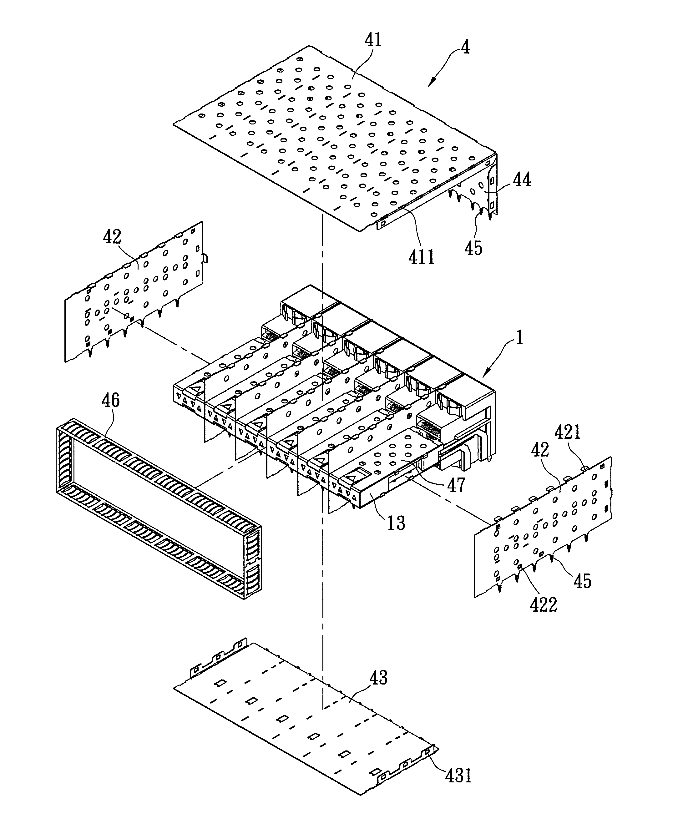
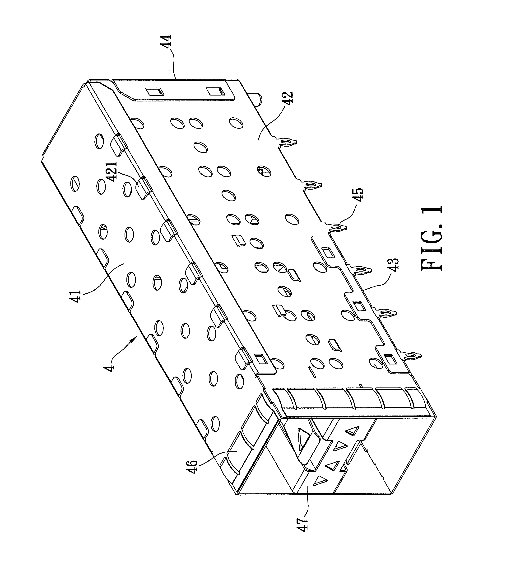
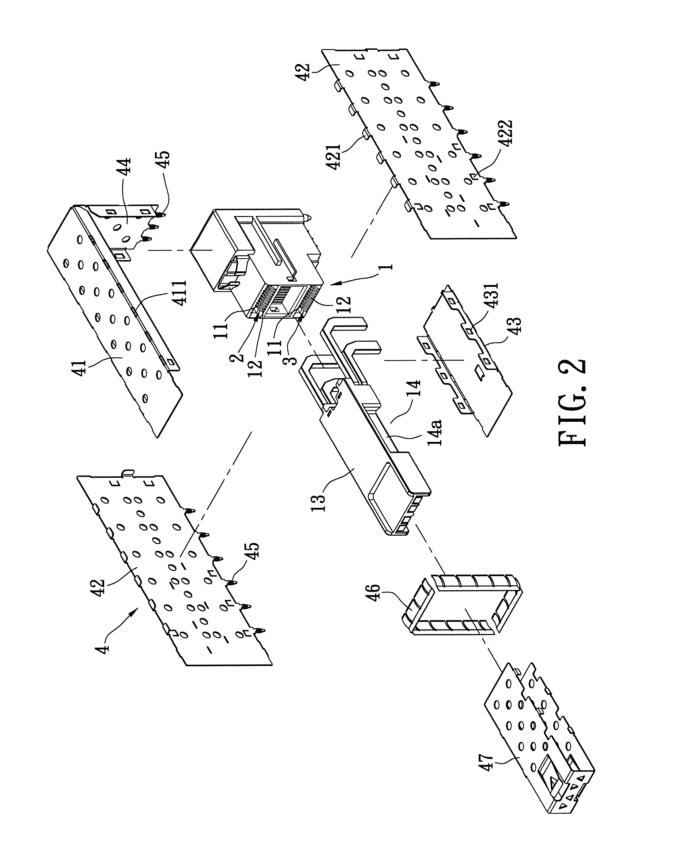
[0024]Please refer to FIGS. 1˜4, wherein the instant embodiment provides a standard small form-factor pluggable (SFP) connector structure. The SFP connector structure can be grouped laterally and is a 2×1 configuration, which comprises: an insulating body (or a body) 1; a plurality of first terminals 2; a plurality of second terminals 3; and a metal cover 4. The insulating body 1 is made of insulating material such as plastic, and two card entry slots 11 are vertically formed and spaced apart thereon. A plurality of terminal slots 12 are formed in each card entry slot 11, specifically at the top and bottom side thereof. A divider 13 protrudes away from the card entry slots 11 of the insulating body 1. In particular, the divider 13 can be assembled or formed integrally as part of the insulating body 1. For the instant embodiment, the divider 13 is assembled to the insulating body 1.
[0025]Dovetail structures 14 are formed at the sides of the divider 13. The dovetail structure 14 may i...
second embodiment
[0030]Please refer to FIGS. 5˜8, wherein the instant embodiment provides a standard small form-factor pluggable (SFP) connector assembly. The SFP connector assembly comprises the insulating bodies 1, wherein each insulating body 1 includes the first terminals 2 and the second terminals 3. The first and second terminals 2, 3 have similar structural configurations as the first embodiment, so no further elaboration is repeated herein.
[0031]Two light pipes 5, 6 can further be disposed on each divider 13. Each light pipe 5, 6 can be a separate unit by itself to guide its own light. The number of light pipes 5, 6 is not restricted. The light pipes 5, 6 are locked to the bottom portion of the divider 13.
[0032]The insulating bodies 1 are disposed in parallel. The dovetail structures 14 of the adjacent sides of the insulating bodies 1 are tail structure 14a and pin structure 14b, for engaging the adjacent insulating bodies 1 (as shown in FIGS. 9 and 10). The aforementioned side cover 42 is d...
PUM
 Abstract
Description
Claims
Application Information
 - R&D
- Intellectual Property
- Life Sciences
- Materials
- Tech Scout
- Unparalleled Data Quality
- Higher Quality Content
- 60% Fewer Hallucinations
Browse by: Latest US Patents, China's latest patents, Technical Efficacy Thesaurus, Application Domain, Technology Topic, Popular Technical Reports.
© 2025 PatSnap. All rights reserved.Legal|Privacy policy|Modern Slavery Act Transparency Statement|Sitemap|About US| Contact US: help@patsnap.com


