Rotating electrical machine

US20100102681A1Inactive Publication Date: 2010-04-29AISIN AW CO LTD

Image

  • Rotating electrical machine
  • Rotating electrical machine
  • Rotating electrical machine

Examples


embodiment

[0026]An embodiment of a rotating electrical machine of the present invention will be described below in detail with reference to the accompanying drawings.

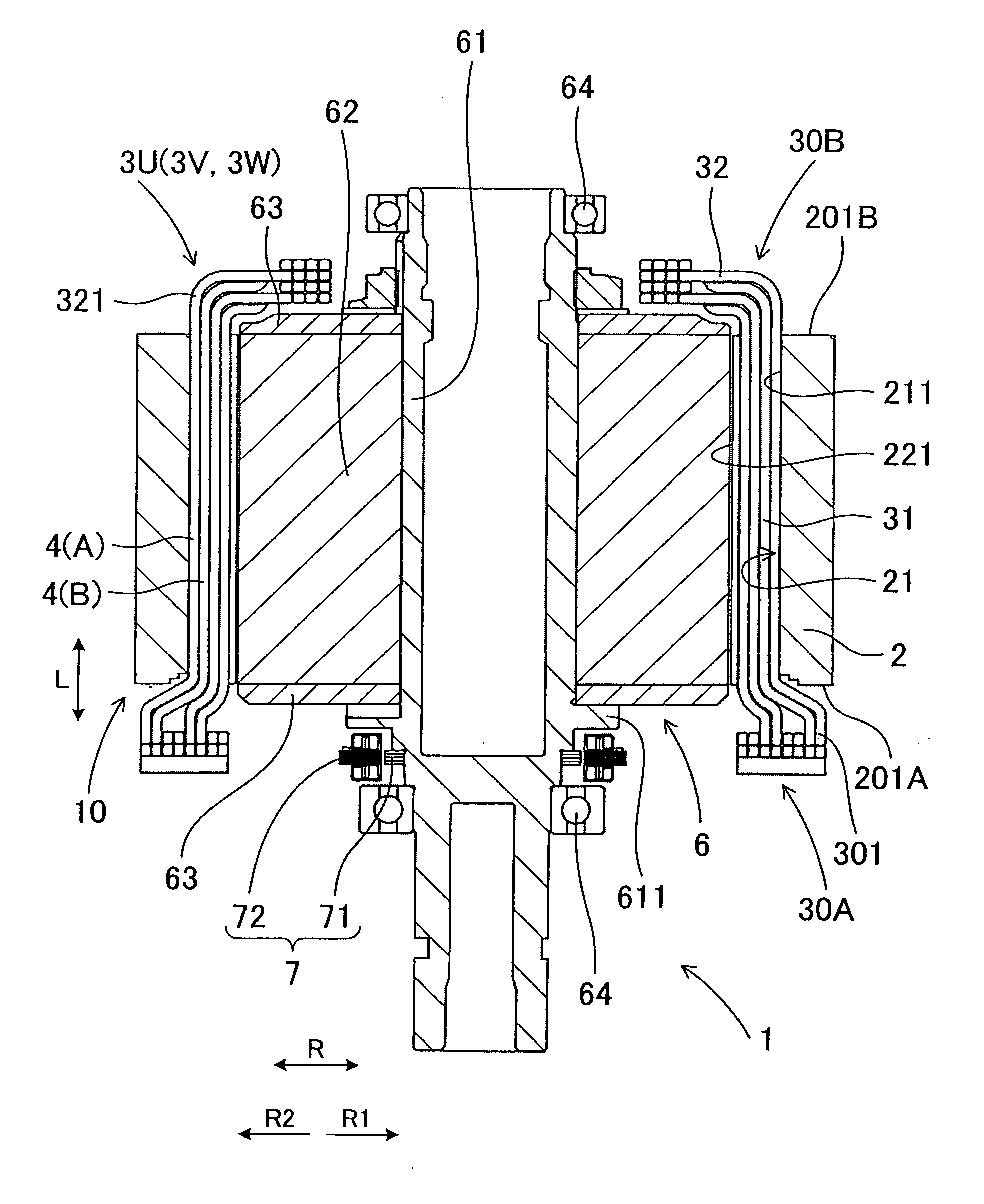
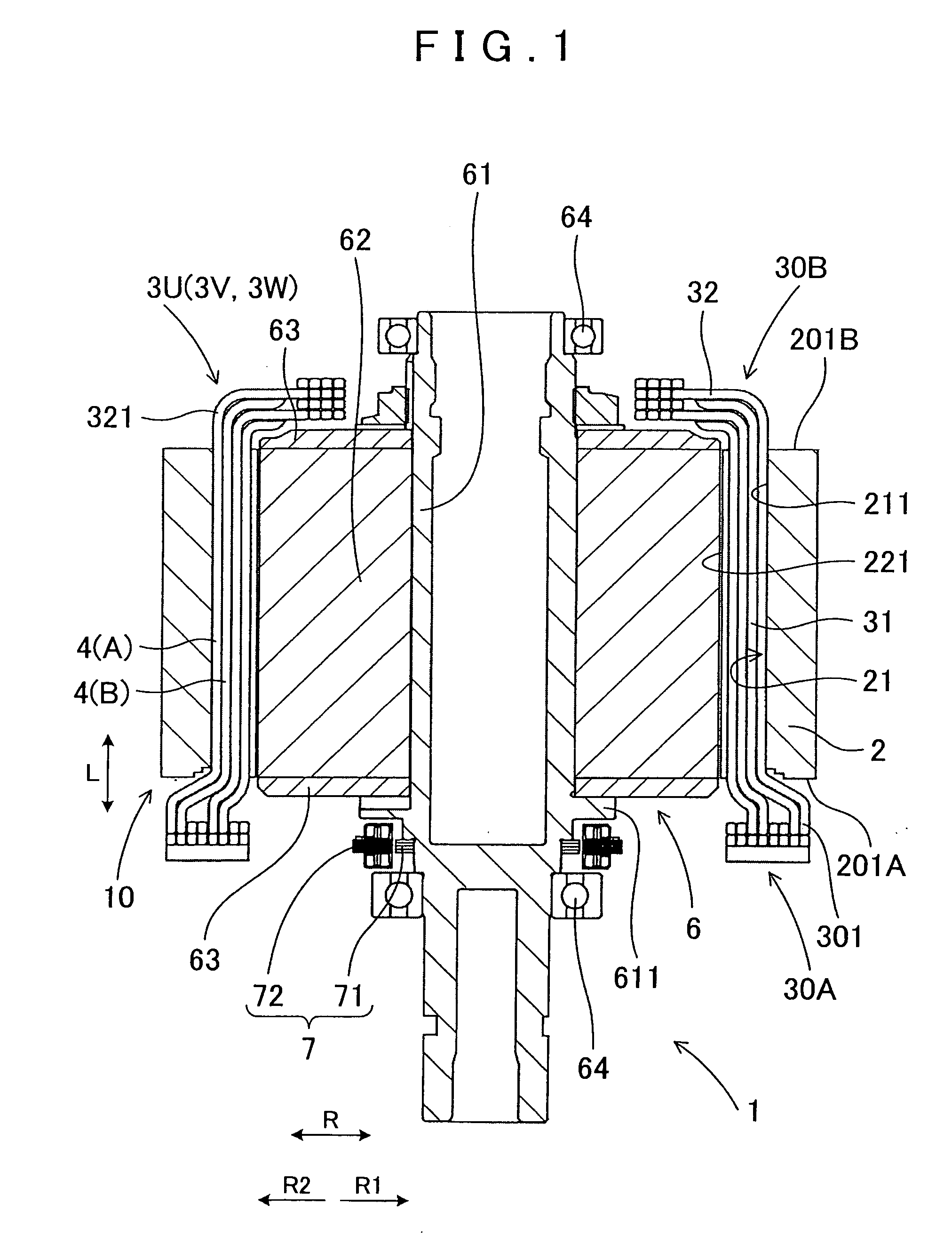
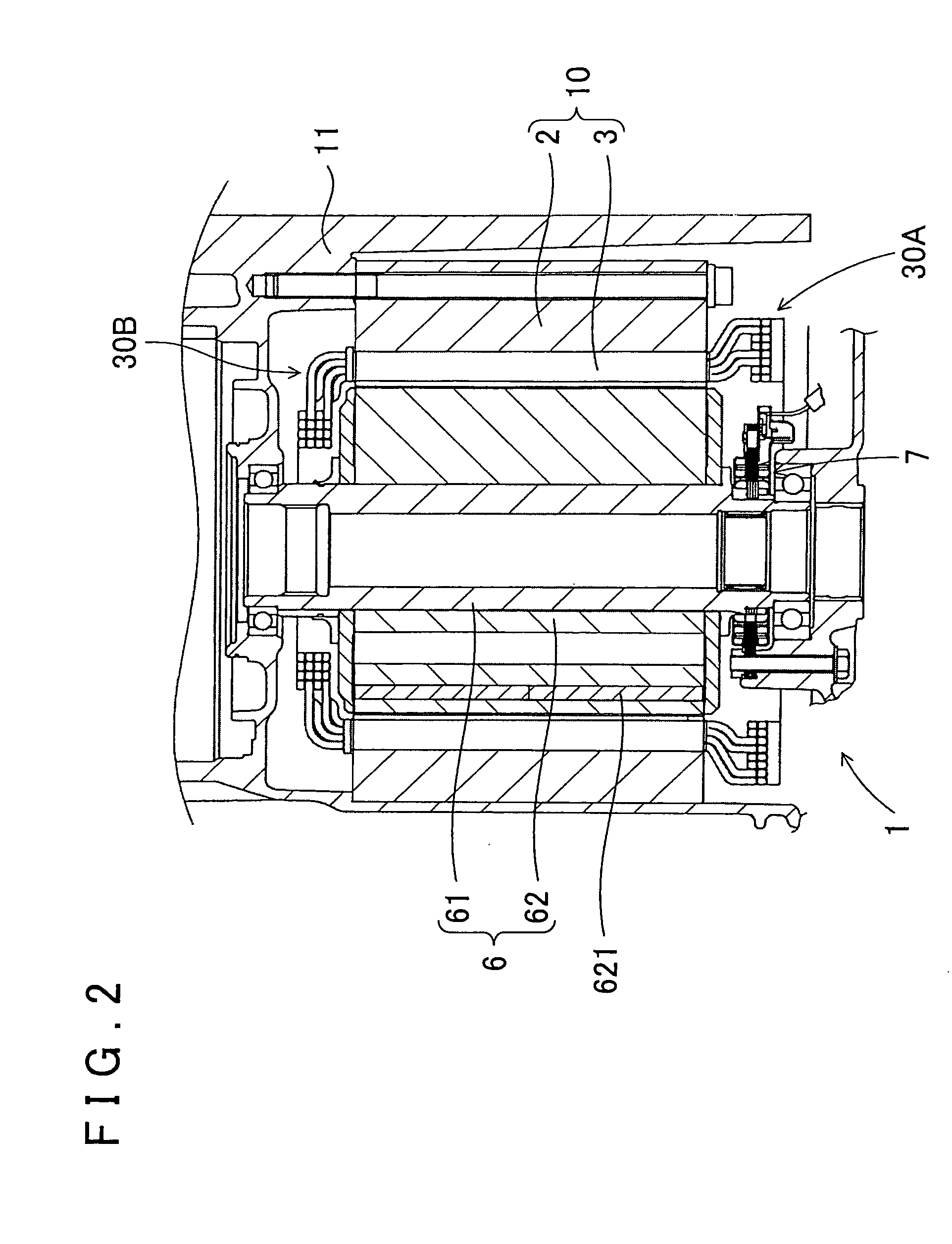
[0027]As shown in FIG. 1, a rotating electrical machine 1 of this embodiment includes a stator 10, which is formed by disposing three-phase coils 3U, 3V, and 3W in a distributed winding state in a plurality of slots 21 formed along an axial direction of a stator core 2, and a rotor 6 rotatably provided on the inner peripheral side of the stator 10.

[0028]As shown in FIGS. 3 and 5, the three-phase coils 3U, 3W, and 3W are disposed so that: in the slots 21 of the same phase, a plurality of coil conductors 4 of the same phase are arranged adjacent to each other in a radial direction R of the stator core 2; in one end-side coil end portion 30A that protrudes from one axial end face 201A of the stator core 2, the plurality of coil conductors 4 of the same phase are arranged on a radially outer peripheral side R2 of an inner peripheral ...


PUM


Abstract

A rotating electrical machine includes a stator formed by disposing coils of a plurality of phases in a plurality of slots formed along an axial direction of a stator core; a rotor rotatably provided on an inner peripheral side of the stator; and a rotation position detector for detecting a rotation position of the rotor disposed on the one axial end side of the stator core.

Description

INCORPORATION BY REFERENCE[0001]The disclosure of Japanese Patent Application No. 2008-273106 filed on Oct. 23, 2008 including the specification, drawings and abstract is incorporated herein by reference in its entirety.BACKGROUND[0002]The present invention relates to a rotating electrical machine including a stator formed by disposing coils of a plurality of phases in slots of a stator core, and a rotor rotatably disposed on the inner peripheral side of the stator.[0003]For example, in a stator for use in a rotating electrical machine, three-phase coils of U-phase, V-phase, and W-phase are disposed in a stator core by using jigs for holding and inserting the three-phase coils on the inner peripheral side of the stator core. After the three-phase coils are disposed in a plurality of slots of the stator core, a coil end conductor portion, which protrudes from an axial end face of the stator core, is deformed radially outward of the stator core.[0004]In a stator manufacturing method o...

Claims


Application Information

Patent Timeline
29 Apr 2010
Publication
US20100102681A1
IPC
H02K11/00
CPC
H02K11/0031; H02K3/12; H02K11/225
Inventors
KOGA, KIYOTAKA; YAMAMOTO, YOSHIHISA