RFID transmitter

Inactive Publication Date: 2010-04-29
SUREFLAP
View PDF14 Cites 9 Cited by
  • Summary
  • Abstract
  • Description
  • Claims
  • Application Information

AI Technical Summary

Benefits of technology

[0017]The RFID interrogator, active RFID tag, or general radio transmitter may incorporate feedback to reduce transient changes in the amplitude of the resonator. Implementation of feedback may improve the speed of response of the interrogator when used as a reader. Also the feedback may reduce transients in the amplitude of the resonator when it is restarted over the course of the modulation of the interrogator field. Alternatively the RFID interrogator may not implement feedback.
[0

Problems solved by technology

Their use increases the efficiency of energy transfer between the two circuits, which would otherwise be much lower, severely limiting the range of operation.
A high Q resonator may not provide sufficient speed of response to allow amplitude modulations at the required rate simply through turn off and turn on of the stimulus.
The drawback of these prior art methods are that the turn on/off time may still be limited, and also they invol

Method used


Image

  • RFID transmitter
  • RFID transmitter
  • RFID transmitter

Examples


Embodiment Construction

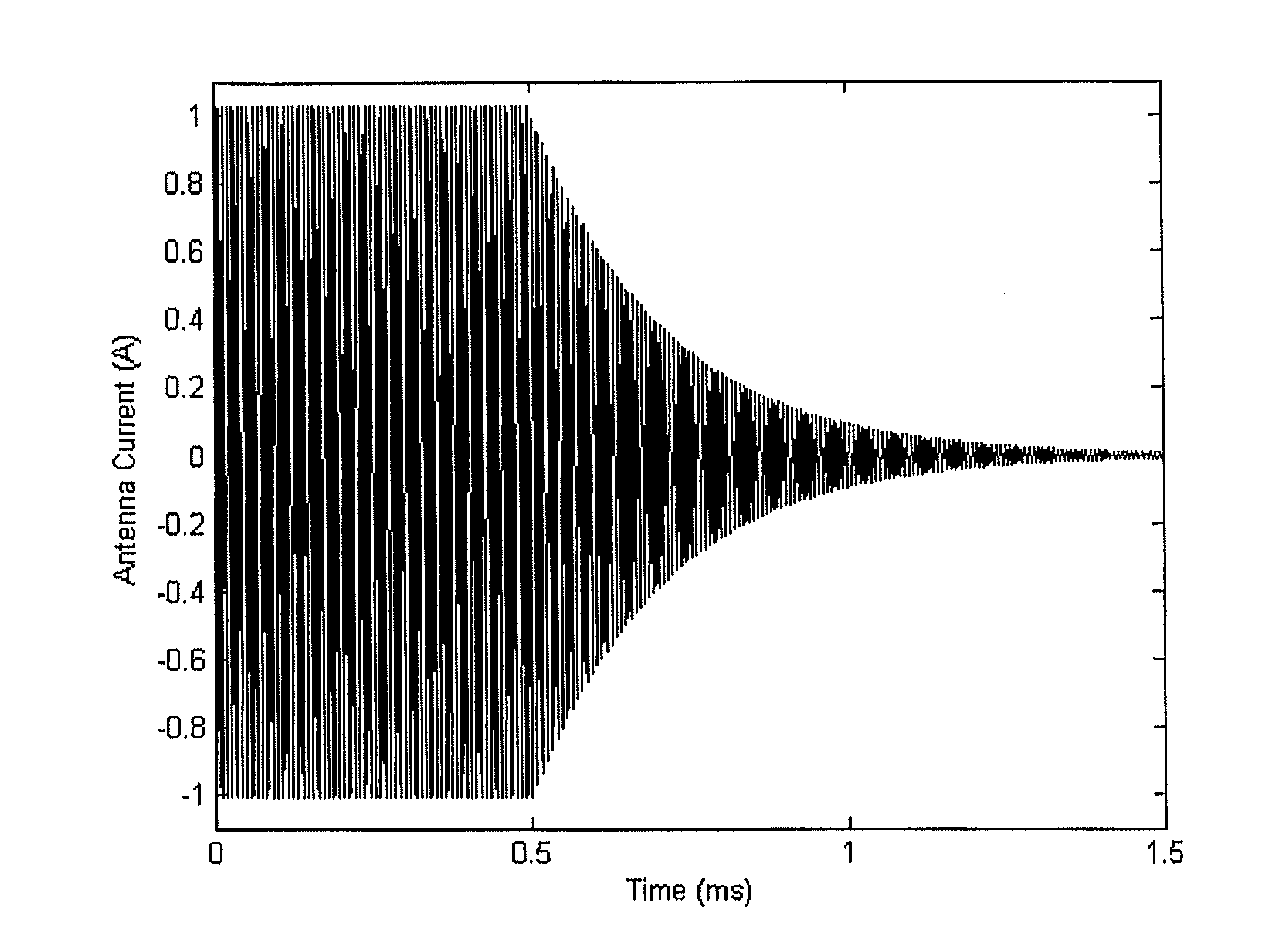
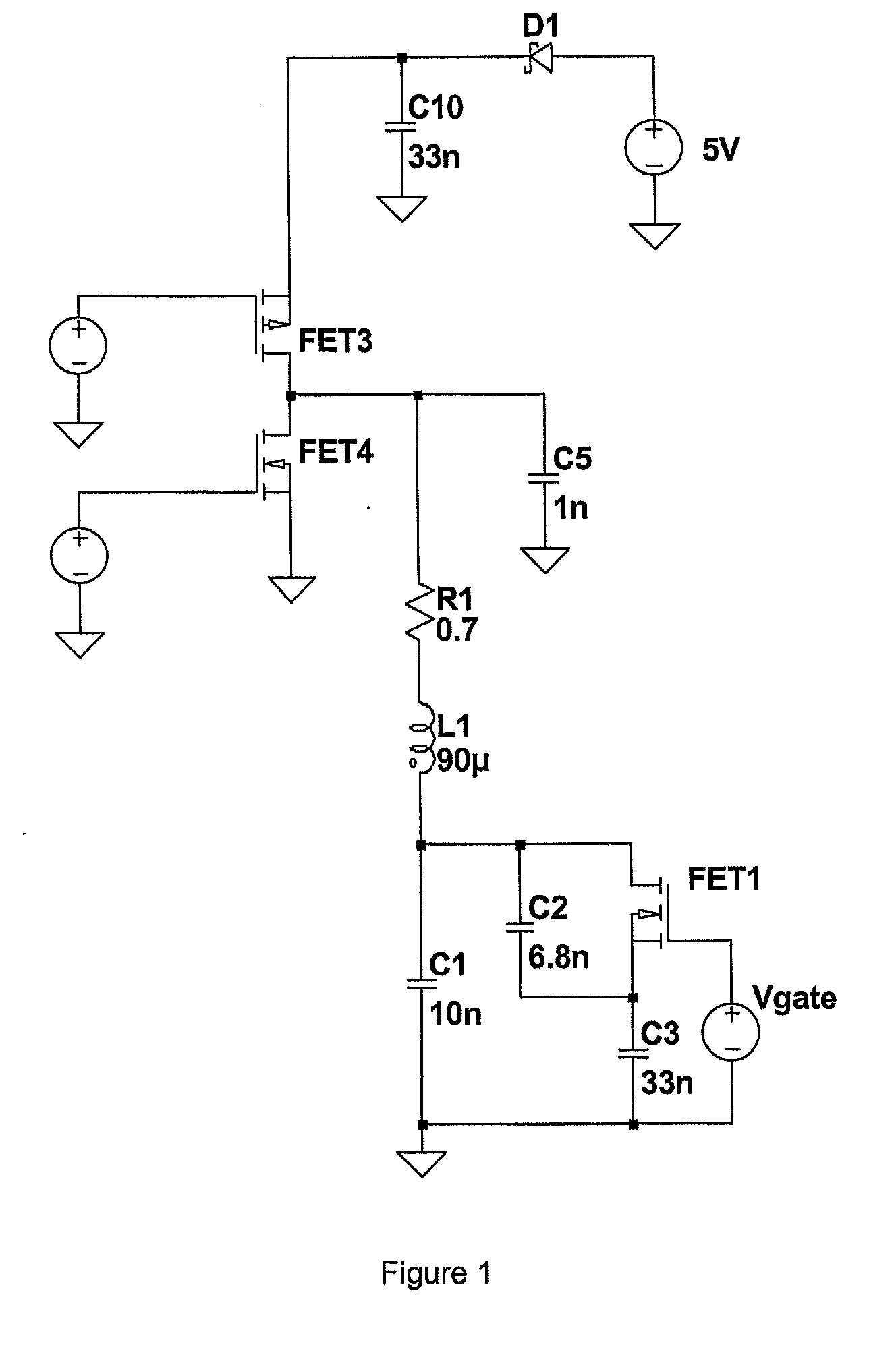
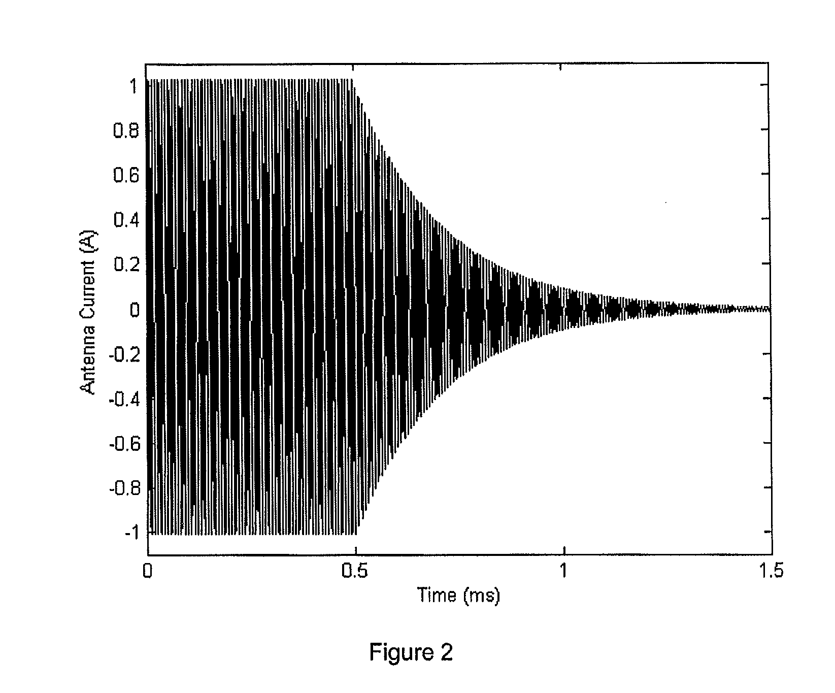
[0045]FIG. 1 shows an embodiment of an RFID interrogator incorporating a nonlinear resonator. The resonator comprises an antenna with inductance 90 mH and series resistance of 0.7Ω, giving a Q at 125 kHz of approximately 100. The antenna is connected to a capacitive network C1, C2, C3 and MOSFET FET1. The capacitive network has two distinct states with the FET1 on and FET1 off. When FET1 is on the total capacitance is 43 nF, since C2 is shorted out, whereas when FET1 is off the total capacitance is 15.6 nF. FET1 is turned on or off depending on the amplitude of the waveform at the source potential, relative to the fixed gate voltage Vgate. The duty cycle of the FET1 on state varies with the resonance amplitude, which naturally adjusts to allow the resonator to match the 125 kHz stimulus frequency. The amplitude of the resonator is controlled through Vgate, increasing as this voltage is reduced to negative voltages.

[0046]The stimulus to the resonator is supplied through the complemen...


PUM


Abstract

Embodiments of the invention relate to the field of RFID interrogators, particularly RFID interrogators that combine low loss with high rates of communication from the interrogator to a tag. Further embodiments relate to the field of active RFID tags and general radio transmitters. We describe a transmitter comprising a resonant circuit and a driver coupled to drive said resonant circuit, wherein said resonant circuit includes a resonance regeneration system such that during amplitude modulation of a resonant signal in said resonant circuit when an amplitude of said resonant signal is reduced energy from said reduction is stored and when said amplitude is increased said stored energy is used to regenerate said resonance signal.

Description

FIELD OF INVENTION[0001]Embodiments of the invention relate to the field of transmitters, particularly RFID transmitters that combine low loss with high rates of communication. Embodiments of the invention include RFID interrogators, active RFID tags, and general radio transmitters.BACKGROUND TO THE INVENTION[0002]In an RFID system resonant circuits are generally used in both the reader and the transponder. Their use increases the efficiency of energy transfer between the two circuits, which would otherwise be much lower, severely limiting the range of operation. Optimal read range may be achieved when the reader is stimulated at its resonance frequency, and this also matches the resonant frequency of the transponder.[0003]The inventor's earlier patent applications PCT / GB2006 / 050436 and PCT / GB2006 / 050440 outline methods that allow the use of a high Q antenna in an RFID reader. These methods prevent the conventional problems of a high Q resonant system associated with a narrow bandwi...

Claims


Application Information

Patent Timeline
IPC IPC(8): H04Q5/22
CPCG06K7/0008H04B1/02H03K17/162
Inventor HILL, NICHOLAS PATRICK ROLAND
Owner SUREFLAP
Why Eureka
Try Eureka