Junction block and link bar

a technology of link bar and junction box, which is applied in the direction of securing/insulating coupling contact members, coupling device connections, electrical devices, etc., can solve the problem that the system cannot withstand high torque, and achieve the effect of avoiding overthickness of the wall, facilitating the insertion of the bar, and strengthening the elasticity of the wall

Inactive Publication Date: 2010-04-29
ABB FRANCE SAS
View PDF3 Cites 0 Cited by
  • Summary
  • Abstract
  • Description
  • Claims
  • Application Information

AI Technical Summary

Benefits of technology

[0012]These arrangements provide a way of obtaining an improved retaining effect, because the retaining contact between the retaining portions is provided at the end of the bar, that is, at the furthest possible point away from the screwing rotation axis.
[0015]This arrangement provides a way of limiting the slipping of the retaining portions relative to each other and of exerting the abutment force along an axis perpendicular to the rotation axis of the screw.
[0021]Advantageously, the wall of the recess includes a protrusion, and an opening close to the protrusion, so as to enhance the elasticity of the wall.
[0023]These provisions facilitate the insertion of the bar into its recess, while ensuring the effectiveness of the retention.
[0025]This arrangement enhances the elasticity of the wall and facilitates the insertion of the bar into the recess while avoiding an overthickness of the wall of the recess in the position of a protrusion.

Problems solved by technology

However, this system cannot withstand high torques.
Furthermore, these hooks generate a bulk over the length of the bar, and make it necessary to use a bigger bar to be able to offer a gripping position for the hooks on the lateral face of the bar.

Method used


Image

  • Junction block and link bar
  • Junction block and link bar
  • Junction block and link bar

Examples


first embodiment

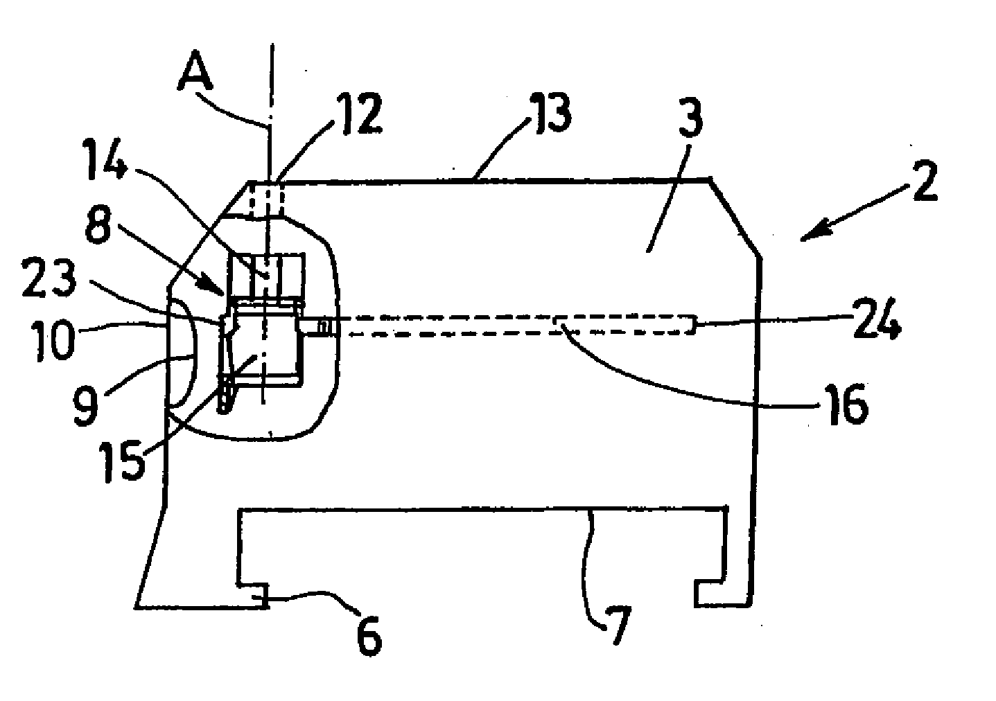
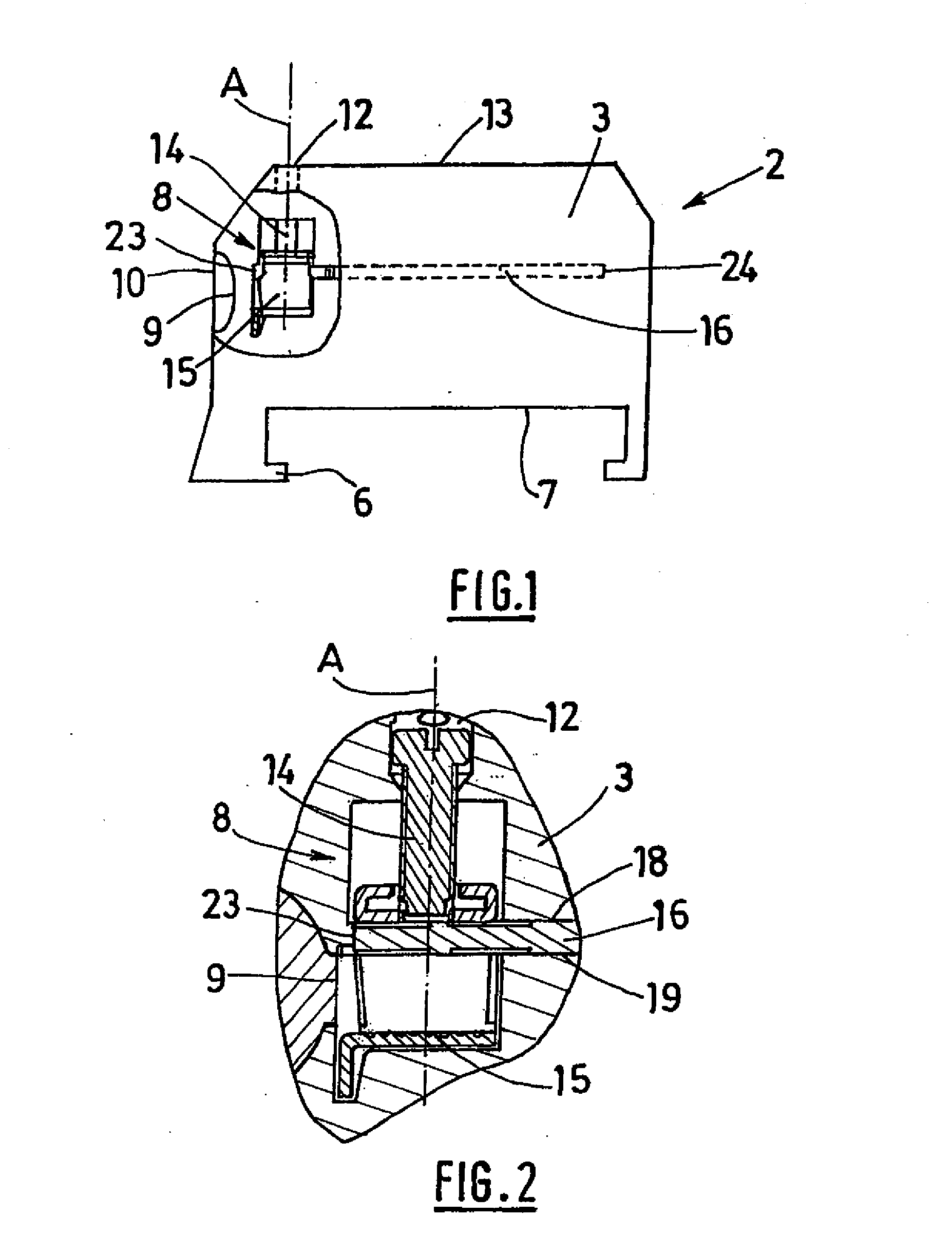
[0034] represented in FIGS. 1 to 3, a junction block 2 according to the invention has an insulating body 3 delimited by parallel lateral faces 4, 5, delimiting a thickness of the block that is less than the dimension of the lateral faces 4, 5. The junction block includes a fixing foot 6 designed to be fixed to a support rail, located on the rear face 7 of the block.

[0035]The junction block 2 also comprises two screw-connection terminals 8, each terminal 8 having an opening for inserting a conductor 9, located on one of the front faces 10 of the junction block, and an opening for inserting a tool 12, located on the face to the front 13 of the junction block, through which an operator can insert a tool of screwdriver type to fasten a fastening screw 14. Each terminal 8 is designed to ensure the connection between a conductor inserted through the conductor-insertion opening and a conductive link bar 16.

[0036]The contact between the conductor and the bar is provided by a clamp 15 driven...

second embodiment

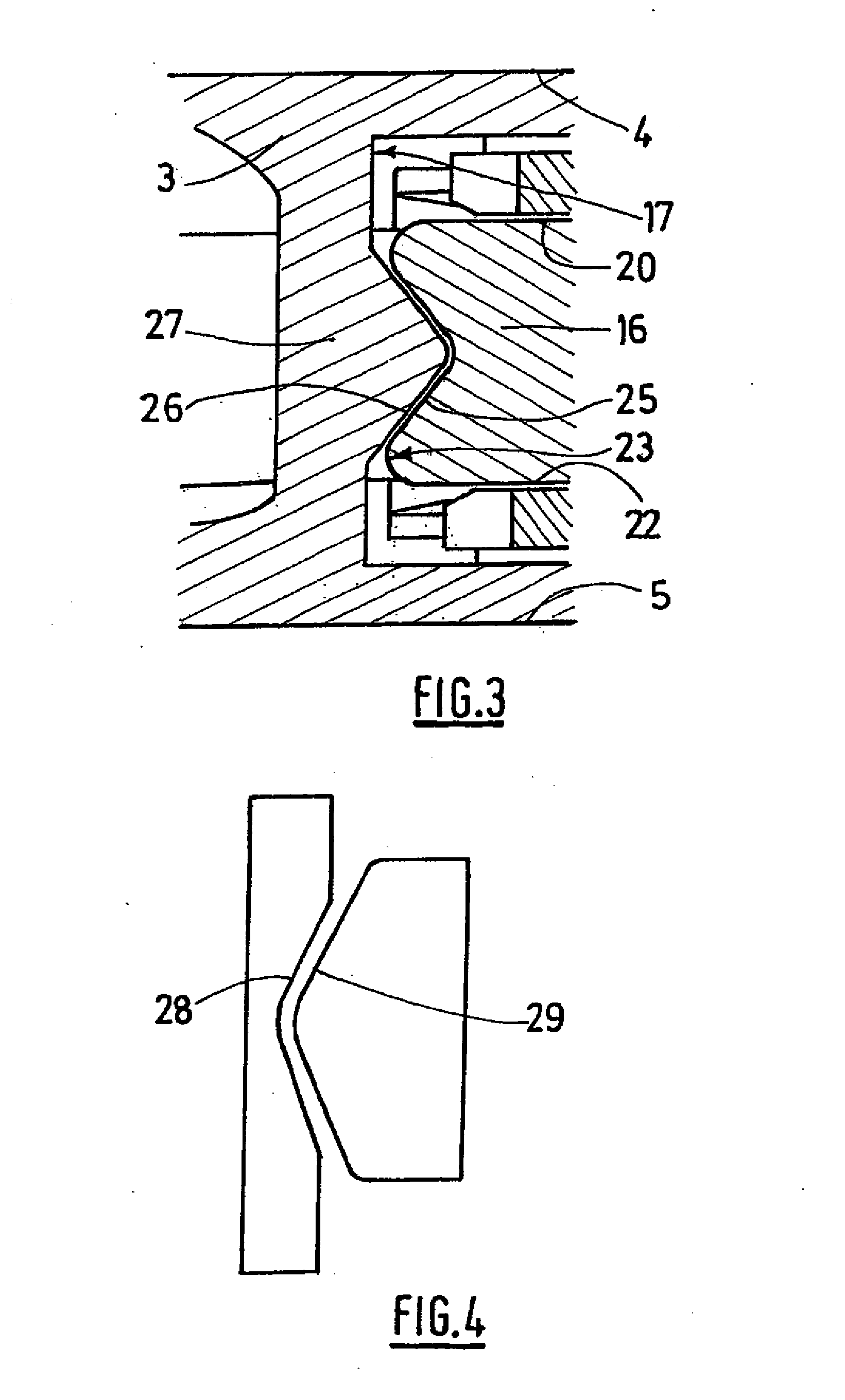
[0043] represented in FIG. 4, the walls include triangular notches 28 and the bar has triangular protrusions 29.

[0044]According to a third embodiment represented in FIG. 5, similar to the first embodiment, the wall 30 has a thickness that is substantially constant level with the retaining portion, which means that a triangular hollow 32 is provided in the wall on the side opposite the protrusion for the elasticity of the insulating support on assembling the bar.

fourth embodiment

[0045] represented in FIG. 6, the retaining portion 33 of the bar comprises a notch having a square profile.

[0046]The retaining portion of the wall of the recess includes a protrusion 34, and an opening 35 close to the protrusion, so as to enhance the elasticity of the wall.

[0047]The protrusion has an oblique face 36 in the direction of insertion of the bar into the recess and a straight face 37 in the direction of removal of the bar.


PUM


Abstract

The invention relates to a junction block that comprises a housing for receiving a conducting linking rod (16). The linking rod (16) includes on at least one end surface (23) a retaining portion (25) having a shape at least partially complementary with a retaining portion (16) of the opposite wall defining the housing (17), the rod retaining portions and the wall of the housing being urged in abutment upon a movement of the rod end towards the outside of the housing (17).

Description

TECHNICAL FIELD OF THE INVENTION[0001]The present invention relates to a link bar, and a junction box comprising such a link bar.BRIEF DESCRIPTION OF RELATED ART[0002]As is known, for example from the document GB815478, a conductive link bar is used in a junction block to electrically link different components of the block.[0003]In particular, the link bar is used to link one or more connection terminals.[0004]In the particular case of screw-connection terminals, to make an electrical contact between a conductor inserted into the terminal, the stripped end of the conductor must be screw-fastened onto the bar or onto an intermediate conductive element in contact with the bar. At the end of the fastening operation, considerable torque may be applied by the fastening means, for example a screwdriver, to the link bar, via a fastening screw.[0005]In these conditions, the bar, under the effect of this torque, may be driven to rotate and leave the recess designed to receive it provided in ...

Claims


Application Information

Patent Timeline
Patent Type & Authority Applications(United States)
IPC IPC(8): H01R31/08
CPCH01R13/42H01R9/26
Inventor SARTORIO, MICHELMOINE, GEOFFREY
Owner ABB FRANCE SAS
Why Eureka
Try Eureka