
Data acquisition apparatus and methodology for self-diagnosing of ac modules

Active Publication Date: 2010-04-29
FTC SOLAR INC
View PDF24 Cites 41 Cited by
  • Summary
  • Abstract
  • Description
  • Claims
  • Application Information

AI Technical Summary

Benefits of technology

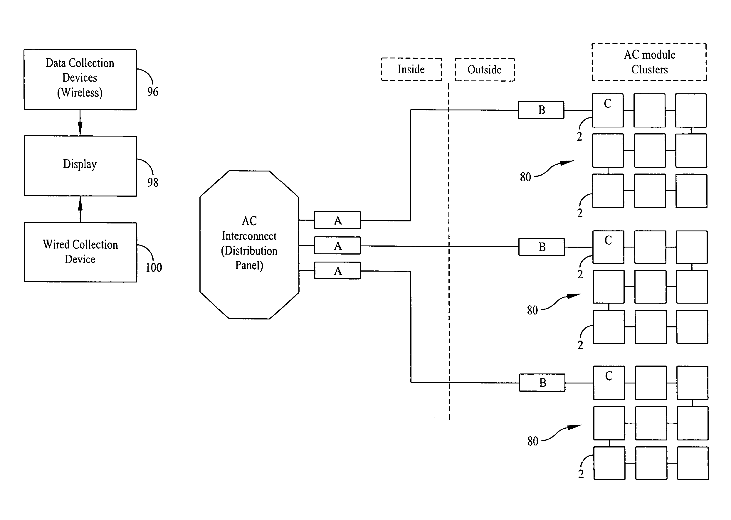
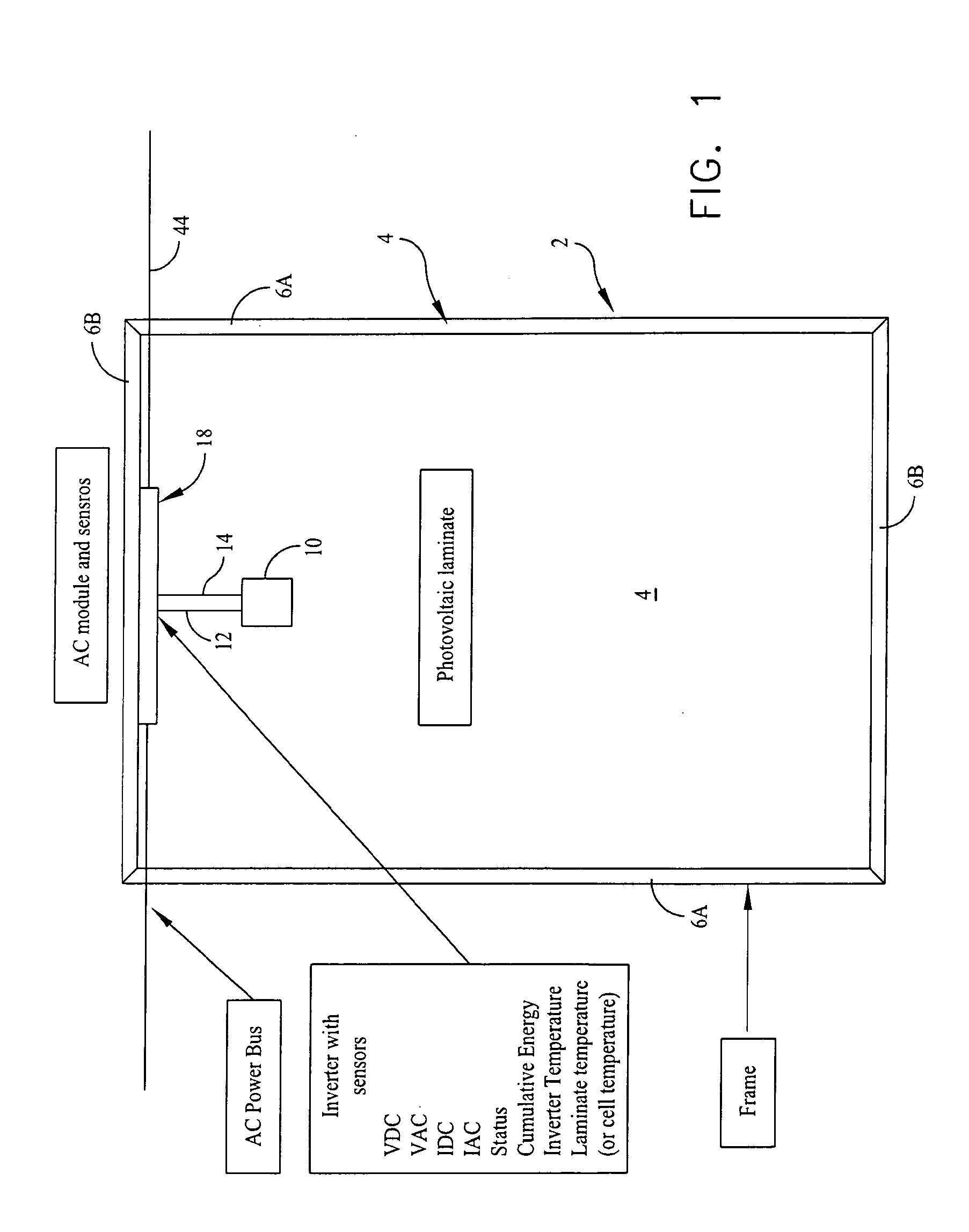
[0018]Still another aspect of the invention is that each AC PV module inverter includes a PV laminate temperature sensor that is embedded at the factory, with each module having the same type of sensor, whereby the inverters of the AC PV modules are able to report identically recorded values of module performance and properties, e.g., DC voltage, DC current, AC voltage, AC current, AC energy, inverter temperature, inverter status, laminate or cell temperature, resulting in data that can be compared among AC PV modules operating in a similar environment, with the measurements being made by each inverter without error-prone field wiring or error-prone installer sensor placement. The apparatus also provides all necessary on-site data storage and communications for the duration of the expected 20-year lifetime of a PV module system.

Problems solved by technology

However, such real-world photovoltaic systems experience performance faults associated with wiring, mounting, orientation, shading, soiling, and snow among others, as well as individual PV module deterioration due to aging, temperature cycling and other factors.
However, power line communications in residential environments pose a number of complex issues.
The primary issue is that the AC power line is inherently a noisy environment.
Energy saving devices often introduce noisy harmonics as well.
Unfortunately current methods of monitoring and diagnosing problems with a PV power generating system comprising a plurality of interconnected PV modules and a single inverter only provide a macro view of the system performance, which includes the inverter, the array and the operating environment as a whole.
Obtaining module level information is too expensive to implement and cumbersome to manage, requiring extensive wiring and additional components such as a temperature sensor for each DC-power generating PV module.
However, heretofore there has been lacking a comprehensive method and apparatus for acquiring data from a plurality of AC PV modules that accomplishes detailed self-diagnosis of each module, including measuring, datalogging and communicating data representing AC PV module performance.

Method used


Image

  • Data acquisition apparatus and methodology for self-diagnosing of ac modules
  • Data acquisition apparatus and methodology for self-diagnosing of ac modules
  • Data acquisition apparatus and methodology for self-diagnosing of ac modules

Examples


Embodiment Construction

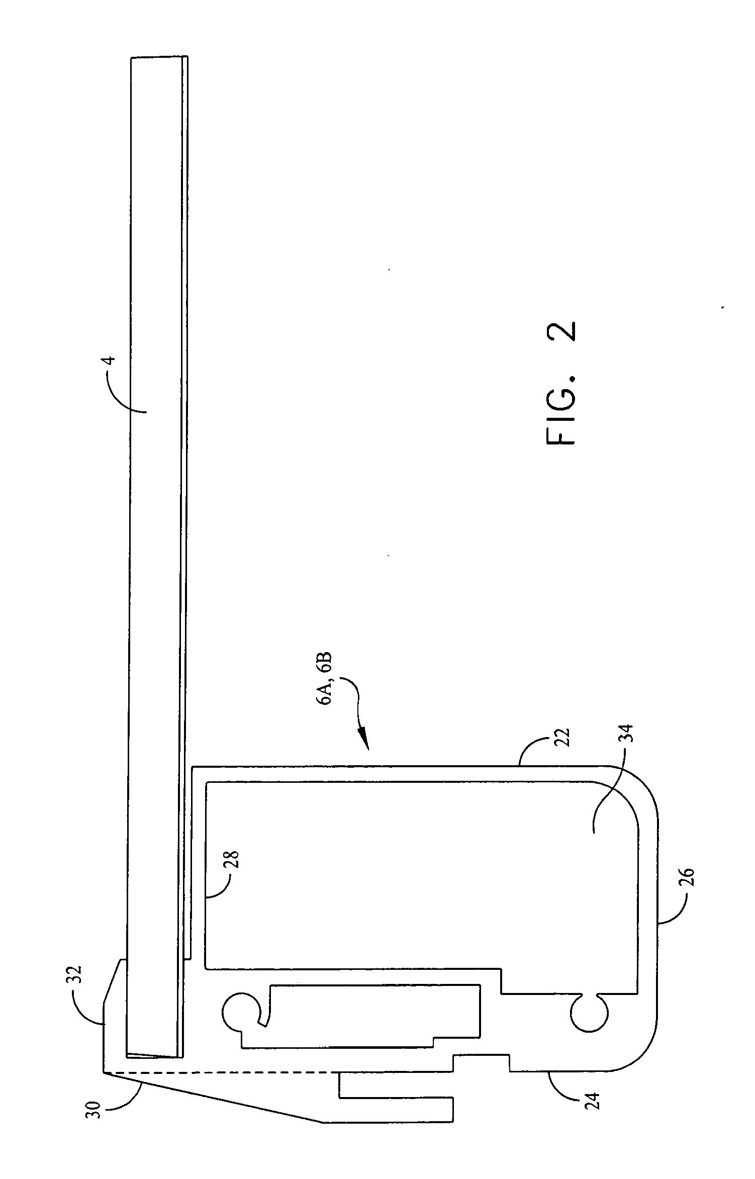
[0033]The present invention is premised on the provision of a plurality of PV modules and a plurality of electrical inverters each disposed to convert the DC power output of an individual module to AC power. Each PV module may comprise a single PV laminate or a plurality of PV laminates. Details of construction of the laminates are omitted since the specific construction of the laminate is not critical to the invention. Accordingly it is to be understood that various forms of PV laminates may be used in the practice of the invention. By way of example but not limitation, the PV laminates may be manufactured as disclosed by U.S. Pat. Nos. 4,499,658, issued Feb. 19, 1985 to K. J. Lewis for Solar Cell Laminates; U.S. Pat. No. 5,733,382, issued Mar. 31, 1998 to J. I. Hanoka for Solar Cell Modules and Method of Making Same; U.S. Pat. No. 5,593,532, issued Jan. 14, 1997 to J. Falk et al. for Process of Manufacturing Photovoltaic Modules; and U.S. Patent Application Publication No. US 2006...


PUM


Abstract

Method and apparatus for monitoring, measuring and recording the operating values of each of a plurality of inter-connected AC PV modules and performing a diagnostic analysis, including comparing the those operating values to each other and to operating values recorded at an earlier time to determine laminate degradation and the performance-attenuating effect of temperature, soiling, shading, and snow cover on the modules.

Description

FIELD OF INVENTION [0001]This invention relates generally to photovoltaic power generating systems and more particularly to an apparatus and method for acquiring and processing performance and related data from a plurality of electrically interconnected AC photovoltaic modules for the purpose of monitoring the state and performance of individual modules and determining the affect on each module from performance-attenuating events.BACKGROUND OF THE INVENTION[0002]Typical photovoltaic power generating installations comprise a plurality of electrically interconnected photovoltaic (PV) modules. An elemental photovoltaic module is comprised of a laminate that includes a plurality of electrically interconnected photovoltaic (solar) cells that generate a DC power output in response to received solar radiation. Commonly a PV module includes a supporting frame that surrounds the laminate at its periphery. The conventional arrangement comprises connecting all of the PV modules in a given inst...

Claims


Application Information

Patent Timeline
IPC IPC(8): H02P31/00
CPCG01R19/2513G01D9/005H02S50/00H02S50/10Y02E10/50
Inventor LITTLE, RUEL DAVENPORTKING, ZACHARY ADAM
Owner FTC SOLAR INC
Learn More