Driving power distribution apparatus and method for controlling torque coupling

a technology of torque coupling and power distribution apparatus, which is applied in mechanical equipment, transportation and packaging, instruments, etc., can solve the problems of controlling for reducing the control target value, seizing affecting the operation of so as to prevent the driving power transmission member from overheating. , to achieve the effect of reliable prevention

Inactive Publication Date: 2010-04-29
JTEKT CORP
View PDF11 Cites 6 Cited by
  • Summary
  • Abstract
  • Description
  • Claims
  • Application Information

AI Technical Summary

Benefits of technology

[0010]Accordingly, it is an objective of the present invention to provide a driving power distribution apparatus and a method for controlling a torque coupling that reliably prevents a driving power transmission member from overheating.

Problems solved by technology

Thus, when the vehicle is traveling a certain condition, for example, when the vehicle continuously travels with a large amount of torque transmission, the driving power transmission member may be overheated.
This can lead to seizing of the driving power transmission member.
Therefore, a determination criterion set without considering such an extended period of high engine load may prevent control for reducing a control target value of the torque transmission amount from being carried out even if heat is accumulated in the driving power transmission member.

Method used


Image

  • Driving power distribution apparatus and method for controlling torque coupling
  • Driving power distribution apparatus and method for controlling torque coupling
  • Driving power distribution apparatus and method for controlling torque coupling

Examples


Embodiment Construction

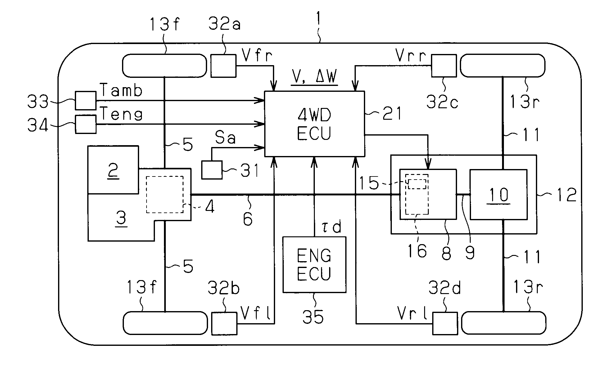
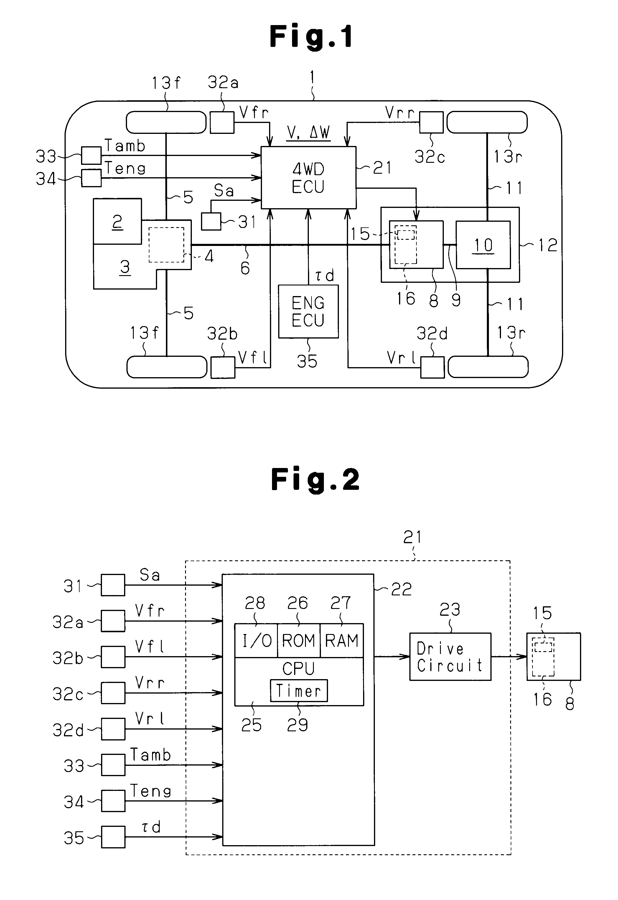
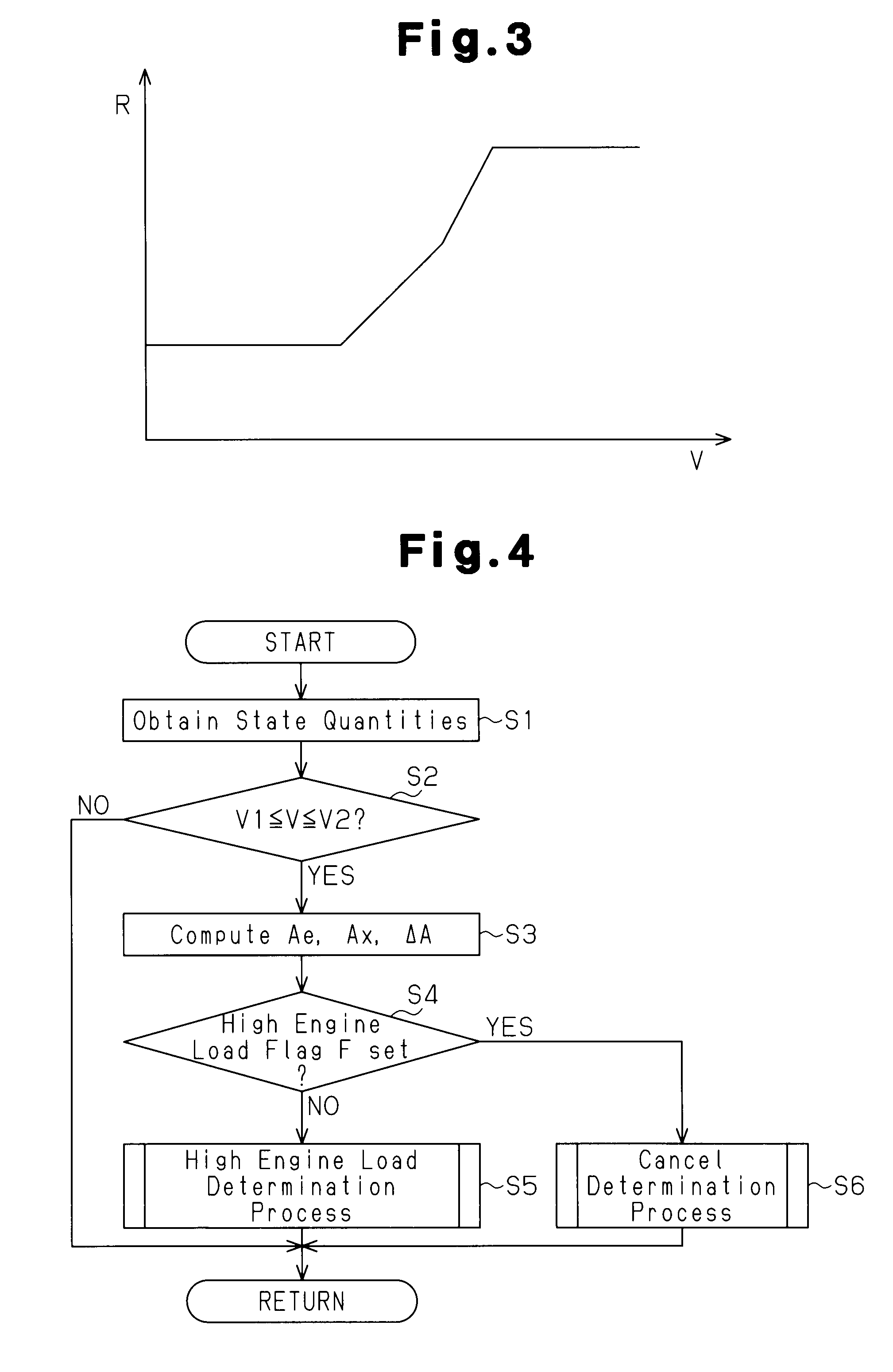
[0022]A driving power distribution apparatus and a method for controlling a torque coupling according to one embodiment of the present invention will now be described with reference to FIGS. 1 to 7.

[0023]As shown in FIG. 1, a vehicle 1 is a front drive-based four-wheel drive vehicle. An engine 2 serving as a driving power source is mounted in a front portion (a left portion as viewed in FIG. 1) of the vehicle 1. A transaxle 3 is attached to the engine 2. The transaxle 3 includes a transfer case 4 and a transmission (not shown). A pair of front axles 5 are coupled to the transaxle 3. A propeller shaft 6 is coupled to the transaxle 3 with the transfer case 4. The propeller shaft 6 can be coupled to a pinion shaft (drive pinion shaft) 9 with a torque coupling 8. The pinion shaft 9 is coupled to a pair of rear axles 11 with a rear differential. A differential carrier 12 is fixed to a frame (not shown) of the vehicle 1. The torque coupling 8, together with the rear differential 10, is ac...


PUM


Abstract

A vehicle 1 has a torque coupling 8, which is located in a driving power transmission system for transmitting the torque of an engine 2 to front and rear wheels 13f, 13r. The torque coupling 8 changes the torque distribution by adjusting the frictional engaging force of an electromagnetic clutch 16. The vehicle 1 also has a 4WD ECU 21 (CPU), which controls the operation of the torque coupling 8 based on the driving state. The 4WD ECU 21 (CPU) estimates a transfer case oil temperature Tptu. When the transfer case oil temperature Tptu is higher than or equal to a first predetermined transfer case oil temperature KTptu1, the 4WD ECU 21 executes overheat prevention control. When the deviation ΔA between an estimated vehicle acceleration Ae, which is computed based on a predetermined vehicle weight M and a driveline torque τd of the engine 2, and the actual vehicle acceleration Av is greater than or equal to a first predetermined deviation KΔA1, the 4WD ECU 21 (CPU) estimates the transfer case oil temperature Tptu to be higher. This allows the control mode of the torque coupling 8 to be smoothly switched to the overheat prevention control.

Description

CROSS-REFERENCE TO RELATED APPLICATIONS[0001]This application is based upon and claims the benefit of priority from prior Japanese Patent Application No. 2008-273009, filed on Oct. 23, 2008, the entire contents of which are incorporated herein by reference.BACKGROUND OF THE INVENTION[0002]The present invention relates to a driving power distribution apparatus and a method for controlling a torque coupling.[0003]Conventionally, driving power distribution apparatuses equipped with a torque coupling have been known. A torque coupling is provided in a driving power transmission system that transmits torque of an engine to wheels. By adjusting the engaging force of a clutch mechanism, the torque coupling changes an amount of transmittable torque, that is, an amount of torque transmission. As one example of such a torque coupling, a torque coupling has been known that includes a first rotating member, which is formed like a cylinder, and a second rotating member, which is formed like a sh...

Claims


Application Information

Patent Timeline
Patent Type & Authority Applications(United States)
IPC IPC(8): F16D48/12
CPCB60K17/35F16D48/06F16D2500/10431F16D2500/30404F16D2500/3065F16D2500/30803Y10T477/6395F16D2500/3109F16D2500/50296F16D2500/7044Y10T477/75Y10T477/6418F16D2500/3107
Inventor MITA, MASAKISHIGETA, RYOHEIKATO, TOMOAKI
Owner JTEKT CORP
Why Eureka
Try Eureka