
Collision reducing device

a technology of collision reduction and reducing device, which is applied in the direction of pedestrian/occupant safety arrangement, vehicular safety arrangement, instruments, etc., can solve the problems of reducing the actuation speed of the collision reduction device, affecting the safety of vehicles, so as to reduce the risk, speed up the collision determination, and reduce the effect of malfunction

Active Publication Date: 2010-04-29
TOYOTA JIDOSHA KK
View PDF3 Cites 21 Cited by
  • Summary
  • Abstract
  • Description
  • Claims
  • Application Information

AI Technical Summary

Benefits of technology

[0005]However, the above-mentioned technique determines the possibility of colliding with the obstacle independently for each instant and thus may incur a fear of malfunctioning such as to carry out a collision mitigation control operation when there is no possibility of collision in practice if the collision reducing device is actuated by once determining that there is a possibility of collision. When the collision reducing device is actuated by a plurality of determinations indicating a collision possibility with reference to determinations in the past, on the other hand, there is a fear of taking time for determinations, thereby retarding the actuation of the collision reducing device.
[0006]In view of such circumstances, it is an object of the present invention to provide a collision reducing device which reduces malfunctions more while securing the speed of collision determination.

Problems solved by technology

However, the above-mentioned technique determines the possibility of colliding with the obstacle independently for each instant and thus may incur a fear of malfunctioning such as to carry out a collision mitigation control operation when there is no possibility of collision in practice if the collision reducing device is actuated by once determining that there is a possibility of collision.
When the collision reducing device is actuated by a plurality of determinations indicating a collision possibility with reference to determinations in the past, on the other hand, there is a fear of taking time for determinations, thereby retarding the actuation of the collision reducing device.

Method used


Image

  • Collision reducing device
  • Collision reducing device
  • Collision reducing device

Examples


Embodiment Construction

[0034]In the following, the collision reducing device in accordance with an embodiment of the present invention will be explained with reference to the accompanying drawings.

[0035]The collision reducing device in accordance with this embodiment is one for detecting automobiles, pedestrians, and the like about a vehicle and carrying out various kinds of control for preventing and mitigating collisions with thus detected objects. FIG. 1 is a block diagram illustrating the structure of the collision reducing device in accordance with this embodiment.

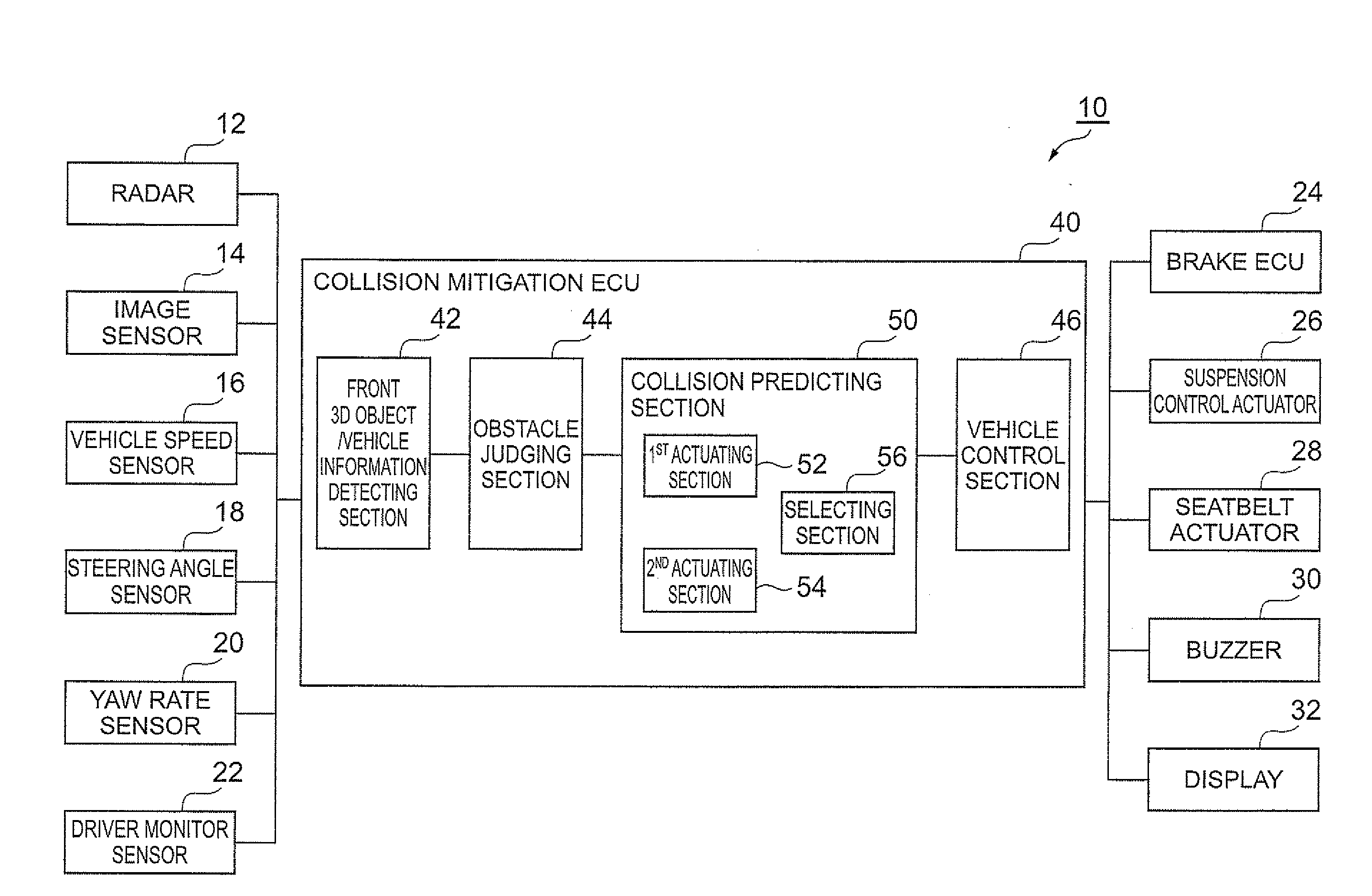
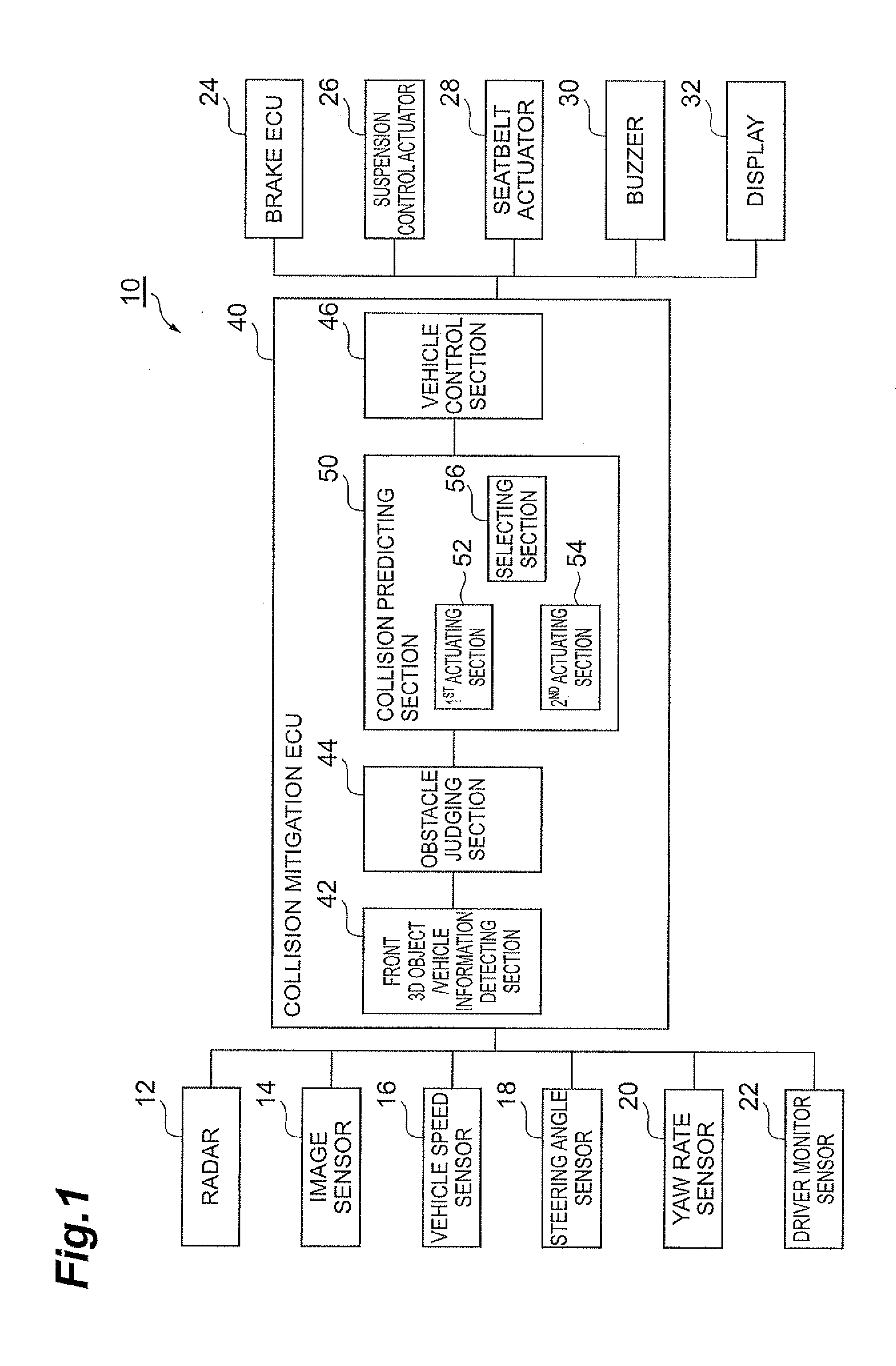
[0036]As illustrated in FIG. 1, the collision reducing device 10 in accordance with this embodiment is mainly constituted by a collision mitigation ECU 40, while various sensors of a radar 12, an image sensor 14, a vehicle speed sensor 16, a steering angle sensor 18, a yaw rate sensor 20, and a driver monitor sensor 22 are connected to the collision mitigation ECU 40. Further, a brake ECU 24, a suspension control actuator 26, a seatbelt act...


PUM


Abstract

A collision reducing device including a radar, an image sensor, a collision mitigation, and a brake. A collision predicting section of the collision mitigation has a first actuating section for causing a vehicle control section to perform running control when a collision possibility exceeds a reference value in one-frame determination, a second actuating section for causing the vehicle control section to perform running control when the collision possibility exceeds a reference value in M-frame determination, and a selecting section for selectively operating the first actuating section and second actuating section, so that the vehicle control section can be operated by two kinds of numbers of determinations, whereby the speed of collision determination can be secured by a smaller number of determinations when operating the first actuating section, while malfunctions can be reduced more by a greater number of determinations when operating the second actuating section.

Description

TECHNICAL FIELD [0001]The present invention relates to a collision reducing device and, in particular, to a collision reducing device which carries out control for reducing influences of collisions by determining a collision possibility between an own vehicle and an object existing about the own vehicle at each discrete time.[0002]1. Background Art[0003]Driving assistance apparatus such as collision reducing device, adaptive cruise control apparatus, and follow-up running apparatus have recently been developed. For example, Japanese Patent Application Laid-Open No. 2005-100232 discloses a technique for determining a possibility of colliding with an obstacle existing in a moving direction of a vehicle, so as to accurately determine the possibility of colliding with the obstacle, thereby effectively actuating a collision reducing device.[0004]2. Disclosure of Invention[0005]However, the above-mentioned technique determines the possibility of colliding with the obstacle independently f...

Claims


Application Information

Patent Timeline
Patent Type & Authority Applications(United States)
IPC IPC(8): G08G1/16B60T7/12B60R21/00
CPCB60R21/0134B60R2021/01259B60R2021/01265B60T7/22G08G1/163B60W2420/52B60W2520/10B60W2520/14G08G1/16B60W2420/403G08G1/166B60W2540/18B60W2420/408
Inventor TSUCHIDA, JUN
Owner TOYOTA JIDOSHA KK
Features
  • Generate Ideas
  • Intellectual Property
  • Life Sciences
  • Materials
  • Tech Scout
  • Unparalleled Data Quality
  • Higher Quality Content
  • 60% Fewer Hallucinations
Learn More