Electric vacuum cleaner

a vacuum cleaner and electric technology, applied in the direction of vacuum cleaners, cleaning equipment, domestic applications, etc., can solve the problems of inability to reduce the effort involved, the suction port portion becomes easily heavy, and the cleaning operation is weary, so as to facilitate the cleaning operation, reduce the burden of cleaning operation, and easily change the direction of the suction port portion.

Inactive Publication Date: 2010-05-06
PANASONIC CORP
View PDF0 Cites 11 Cited by
  • Summary
  • Abstract
  • Description
  • Claims
  • Application Information

AI Technical Summary

Benefits of technology

[0005]An object of the invention is to provide an electric vacuum cleaner capable of changing a direction of a suction port portion to a desired changing direction and reducing the burden applied to a user's wrist.
[0007]According to the invention, the rotary brush unit includes two rotary shaft bodies, and the rotation speed difference generating mechanism generates a difference in the rotation speed between two rotary shaft bodies. For this reason, it is possible to easily change the direction of the suction port portion to the desired changing direction. Accordingly, since it is possible to remarkably reduce a burden during a cleaning operation, it is possible to more comfortably perform the cleaning operation which is a comparatively heavy labor in the housework.

Problems solved by technology

However, since the electric vacuum cleaner is equipped with a motor for driving the rotary brush, it is disadvantageous in that the suction port portion easily becomes heavy and the cleaning operation is wearisome.
For this reason, it is not possible to reduce the effort involved.
Particularly, in an upright cleaner having a heavy suction port portion, it takes a good deal of effort to change the direction of the suction port portion.
Since the direction of the suction port portion is frequently changed during an actual cleaning operation, particularly at this time, a large burden is applied to the wrist.
As a result, the wrist feels fatigued after a long-time cleaning operation.

Method used


Image

  • Electric vacuum cleaner
  • Electric vacuum cleaner
  • Electric vacuum cleaner

Examples


first embodiment

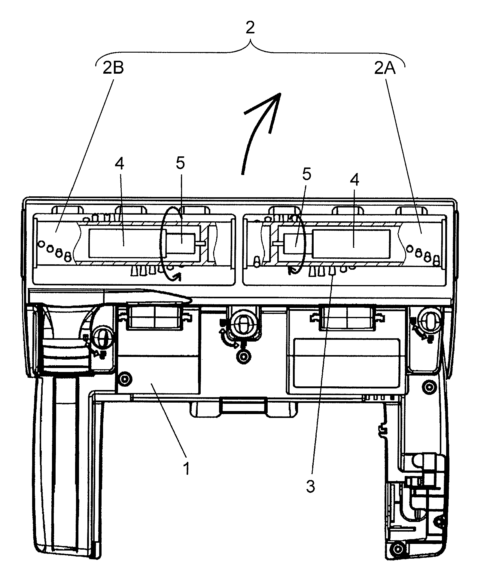
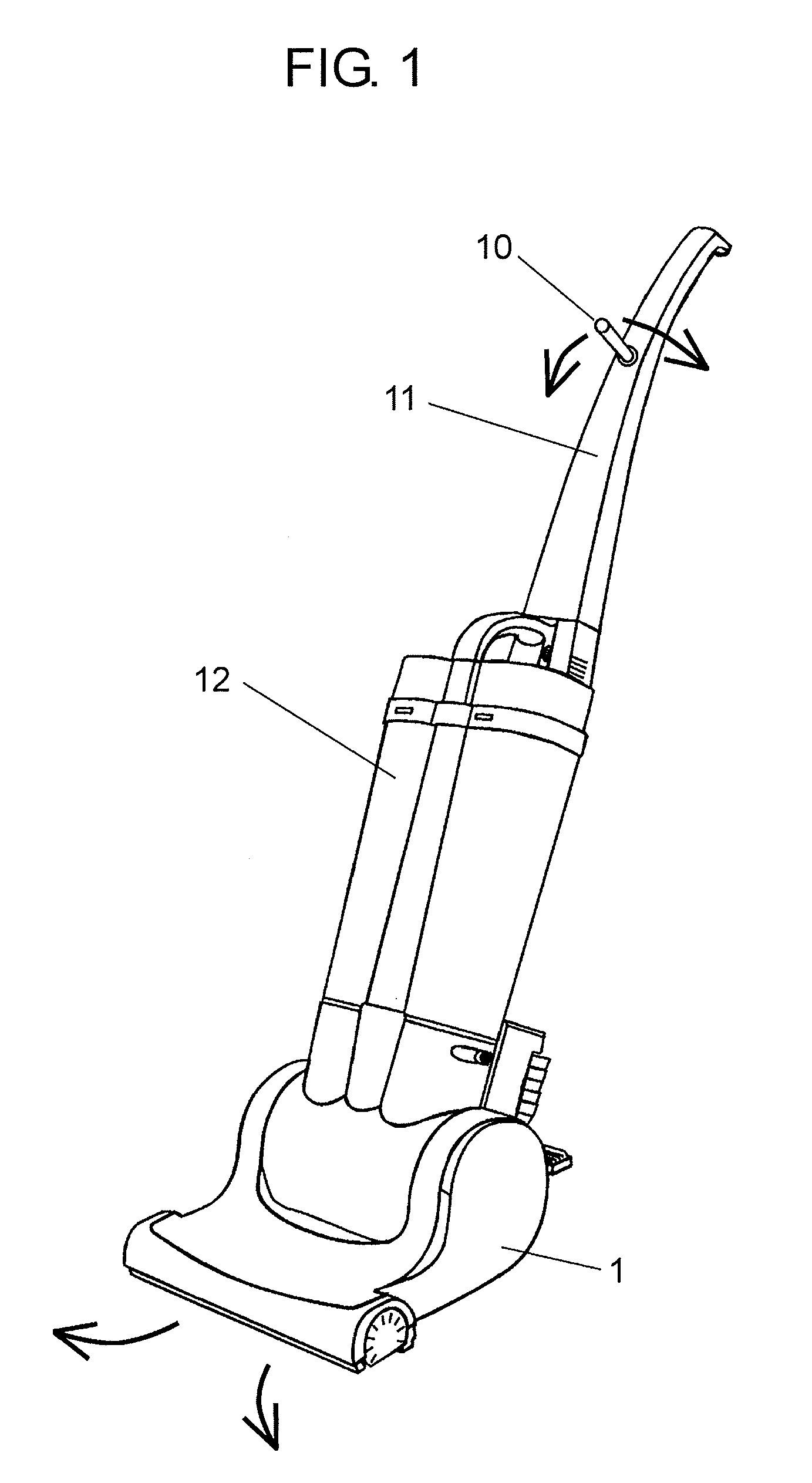
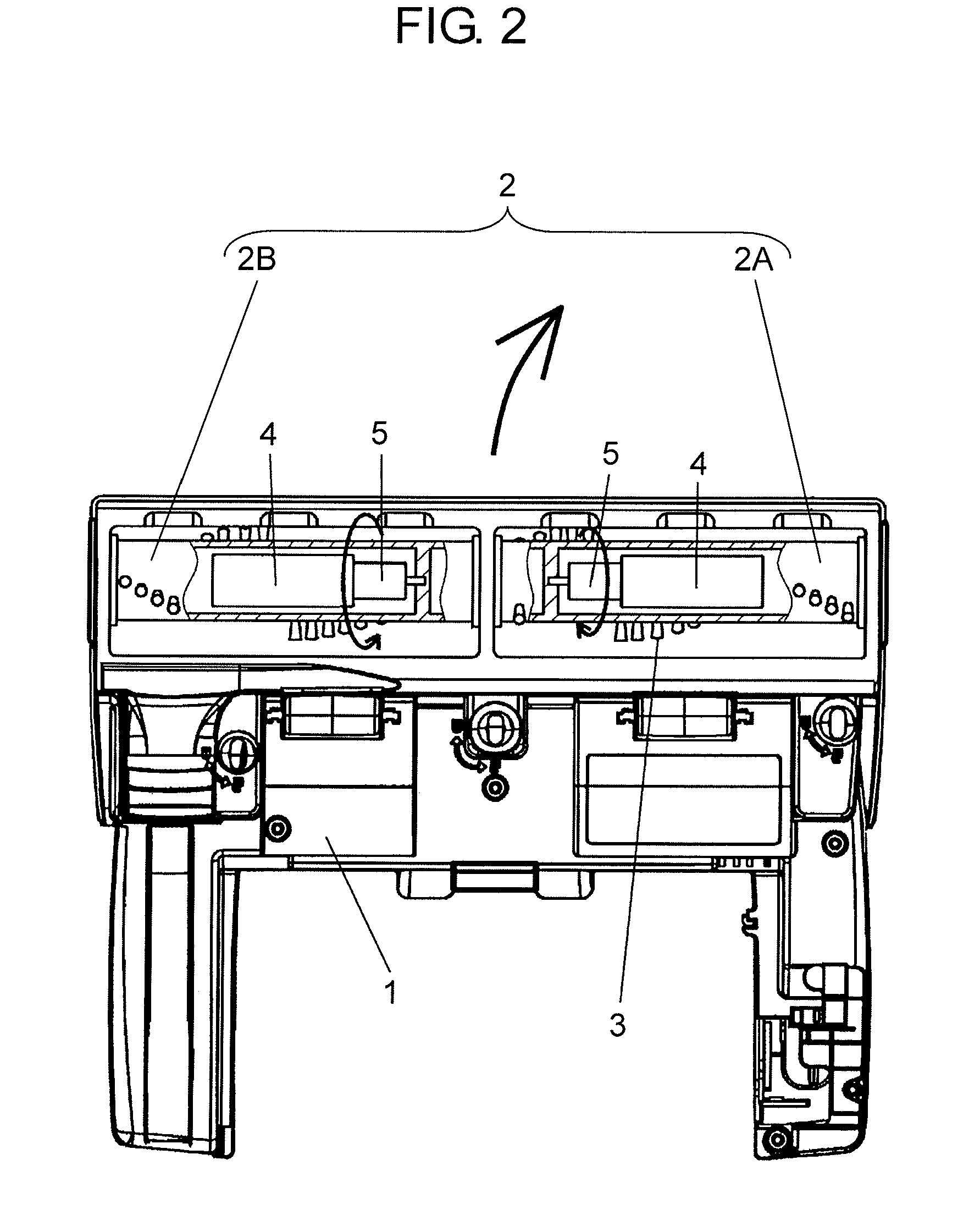
[0018]FIG. 1 is an entire perspective view showing a cleaner body portion of an electric vacuum cleaner according to a first embodiment of the invention. FIG. 2 is a partially sectional view showing a suction port portion according to the embodiment when seen from the bottom of the suction port portion.

[0019]As shown in FIG. 1, an electric vacuum cleaner according to this embodiment includes suction port portion 1 which sucks dust, handle portion 11 which moves suction port portion 1, and cleaner body portion 12 of which a lower portion is provided with suction port portion 1 and an upper portion is provided with handle portion 11. Cleaner body portion 12 includes an electric blower for generating a suction wind. Suction port portion 1 sucks dust together with the suction wind generated by the electric blower. Switch lever portion 10 is attached onto handle portion 11. Switch lever portion 10 is attached to a position where switch lever portion 10 is operable by a finger when grippi...

second embodiment

[0037]FIG. 4 is an entire perspective view showing the electric vacuum cleaner according to a second embodiment of the invention. This embodiment is different from the first embodiment in that switch lever portion 10 is not provided. Instead of switch lever portion 10, handle portion 11 which is twistable in the left and right direction is provided. The rotation speed of two rotary shaft bodies 2A and 2B disposed in rotary brush unit 2 inside suction port portion 1 is controlled through the electric controller (not shown) so that the direction of suction port portion 1 is changed to the twisting direction of handle portion 11. When the twisting amount becomes large, the difference in the rotation speed between rotary shaft bodies 2A and 2B becomes large, and the turning amount becomes large. In the case where handle portion 11 is not twisted, suction port portion rotates forward. Since the other configurations are same as those of the first embodiment, detailed description thereof w...

third embodiment

[0039]FIG. 5 is a plan view showing rotary brush unit 2 inside suction port portion 1 of the electric vacuum cleaner according to a third embodiment of the invention. Rotary shaft bodies 2A and 2B constituting rotary brush unit 2 are rotatably connected to each other through connection portion 30. Connection portion 30 is formed as a simple bearing, and a difference in the rotation speed between rotary shaft bodies 2A and 2B is absorbed by connection portion 30. Brush 3 is attached to surfaces of rotary shaft bodies 2A and 2B.

[0040]Stiff brushes 3A depicted by the solid line are attached to predetermined ranges 101 of rotary brush unit 2. Soft brush 3B depicted by the dotted line is attached to predetermined ranges 102 at the center of rotary brush unit 2. Since the other configurations are the same as those of the first embodiment, detailed description thereof will be omitted.

[0041]With such a configuration, since a large self-propelling force is generated at a position far from th...


PUM


Abstract

Provided are rotary brush unit which is disposed inside suction port portion and in which two rotary shaft bodies each having brush are disposed in series and driving motor which separately rotates each of the rotary shaft bodies. With such a configuration, since it is possible to change a self-propelling direction of the suction port portion to the left and right direction in addition to the forward direction, it is possible to remarkably reduce the effort involved in an operation of changing the direction of the suction port portion.

Description

RELATED APPLICATIONS[0001]This application claims priority under 35 U.S.C. §119 to Japanese Patent Application No. JP2008-282714 filed on Nov. 4, 2008, the entire content of which is hereby incorporated by reference.TECHNICAL FIELD[0002]The present invention relates to an electric vacuum cleaner having a suction port portion and a handle portion.BACKGROUND ART[0003]In an existing electric vacuum cleaner, dust collecting performance using a sweeping-up rotary brush is good in regards to a floor surface and particularly a carpet surface. However, since the electric vacuum cleaner is equipped with a motor for driving the rotary brush, it is disadvantageous in that the suction port portion easily becomes heavy and the cleaning operation is wearisome. In order to solve the disadvantage, for example, Japanese Patent Unexamined Publication No. 2-7923 discloses a technology in which a suction port portion is provided with a self-propelling roller or a rotary brush itself is actively brought...

Claims


Application Information

Patent Timeline
Patent Type & Authority Applications(United States)
IPC IPC(8): A47L5/26
CPCA47L9/0411
Inventor ODACHI, TORUKIKKAWA, TATSUO
Owner PANASONIC CORP
Why Eureka
Try Eureka