Drying hopper

a technology of drying hopper and drying air, which is applied in the direction of drying machines, drying, light and heating equipment, etc., can solve the problem of wasting a large amount of dry air and a large amount of moisture absorption capacity

Inactive Publication Date: 2010-05-06
SYSKO
View PDF15 Cites 7 Cited by
  • Summary
  • Abstract
  • Description
  • Claims
  • Application Information

AI Technical Summary

Benefits of technology

[0018]According to the invention stated in claim 1, a counter-flow contact over a plurality of stages of a number of granular resin materials with dry air within the hopper main body for a long period of time as compared to that attainable under the conventional art allows the moisture contained in the number of granular resin materials to be effectively absorbed by the dry air such that the number of granular resin materials are thoroughly dried before being discharged to the outside of the drying hopper to be fed to an injection molding machine, or the like, for being injection molded, simplification of the configuration has been realized, and a high-performance drying hopper which, when comprehensively viewed, contributes to shortening the drying time can be realized and provided.
[0019]According to the invention stated in claim 2, on the basis of a simple configuration in which, within the hopper main body, inverted cone-shaped hopper parts are arranged in three stages, and cone-shaped material dispersion elements are arranged in three stages, a drying hopper which offers the same advantages as those of the invention stated in claim 1 can be realized and provided.
[0020]According to the invention stated in claim 3, the same advantages as those of the invention stated in claim 2 are offered; in addition, the air flow rate for the dry air and the dew-point temperature of the same are monitored by the air flow meter and the dew-point hygrometer, respectively, and when the measurement is not suitable, the alarming device gives an alarm, thus a drying hopper which can realize the proper quality control of the resin materials to be fed to an injection molding machine, or the like can be realized and provided.

Problems solved by technology

However, the period of time during which the dry air is contacted with the resin materials P is so short that the resin materials P cannot be sufficiently dried, and thus there have been problems that the dry air which has not yet used up its moisture absorption capacity is discharged as it is, the resin materials P is required to be dried once again, part of the moisture absorption capacity of the dry air is wasted, and the like.

Method used


Image

  • Drying hopper
  • Drying hopper
  • Drying hopper

Examples


embodiment

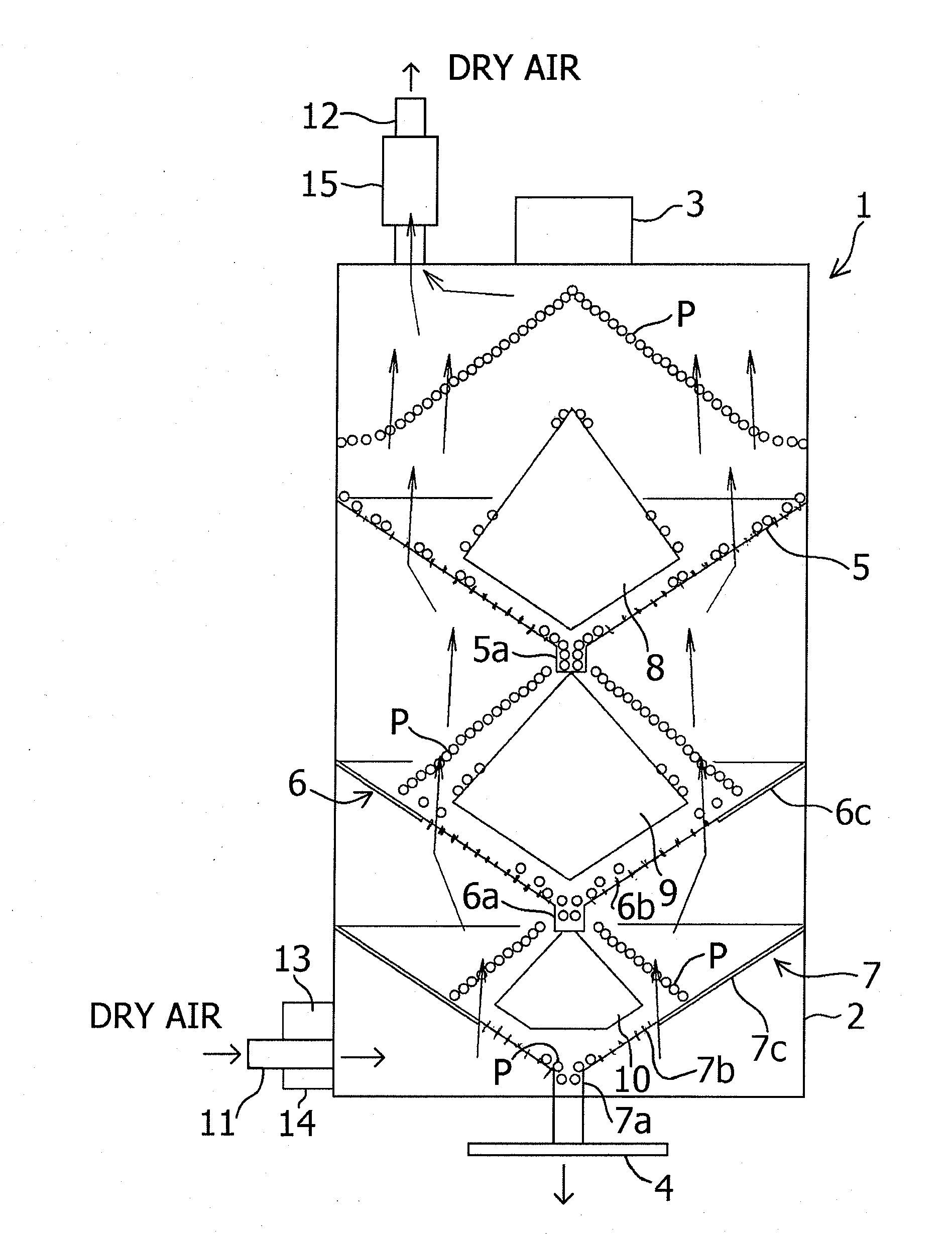
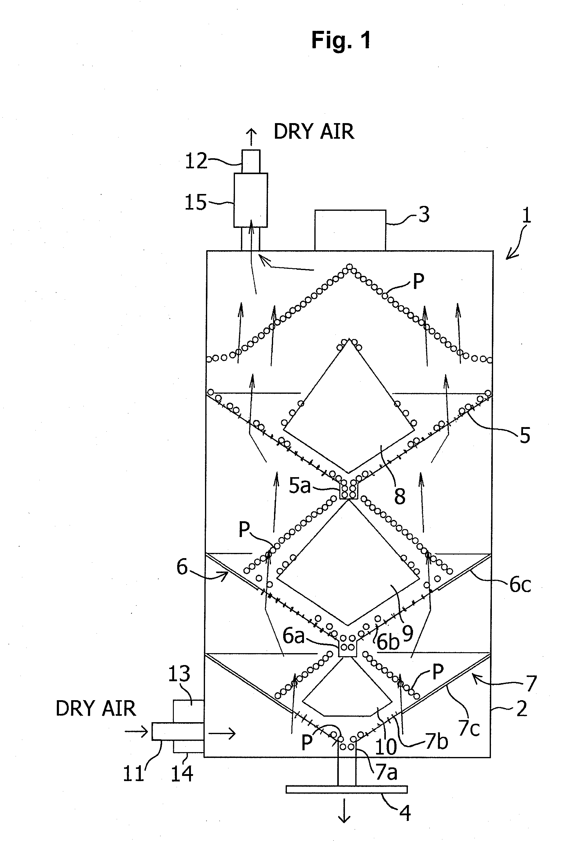
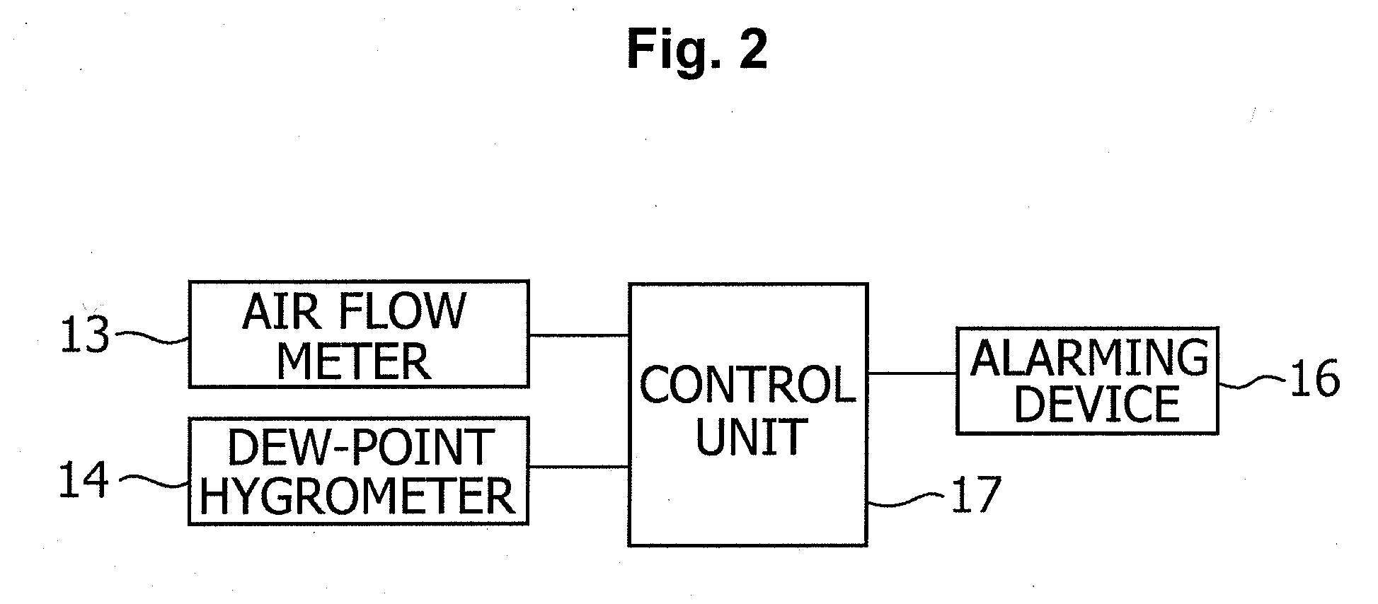
[0023]Hereinbelow, a drying hopper pertaining to an embodiment of the present invention will be explained in detail with reference to FIG. 1 and FIG. 2.

[0024]As shown in FIG. 1, a drying hopper 1 pertaining to the present embodiment is comprised of a tower-shaped (for example, cylindrical) hopper main body 2 having a material charging port 3 at a top portion thereof and a material discharging port 4 at a bottom portion thereof; and a first hopper part 5, a second hopper part 6, and a third hopper part 7 which are arranged in this order at intervals from top to bottom within this hopper main body 2, each being formed substantially in the shape of an inverted cone.

[0025]The first hopper part 5 is formed, as a whole, of a mesh material through which air can be ventilated, and in the central area of a bottom portion of the first hopper part 5, a cylindrical flow pass tube part 5a through which granular resin materials P of, for example, polycarbonate resin, or the like are passed is pro...


PUM

PropertyMeasurementUnit
temperatureaaaaaaaaaa

Abstract

[Problem to Be Solved] The present invention realizes and provides a drying hopper which, with the construction of the hopper itself being simplified, allows the absorption capacity of the dry air to be effectively utilized for improving the drying efficiency and the drying time for the resin materials to be shortened.
[Solution] The drying hopper 1 pertaining to the present invention comprises a tube-shaped hopper main body 2 having a material charging port 3 at a top portion thereof and a material discharging port 4 at a bottom portion thereof; a first hopper part 5, a second hopper part 6 and a third hopper part 7 which are arranged in this order at intervals from top to bottom within this hopper main body 2, each being formed substantially in the shape of an inverted cone, and through which dry air is capable of being ventilated, and granular resin materials P are capable of being passed; first to third material dispersion elements 8 to 10 for dispersing the granular resin materials P that are each disposed under the material charging port 3, and above the top surface of the respective first to third hopper parts 5, 6, 7; a dry air supply/discharge system which forms a dry air ventilation path running from the bottom portion of the hopper main body 2 to above the first material dispersion element 8 through the third hopper part 7, the second hopper part 6, and the first hopper part 5, and leading to the outside of the hopper main body 2.

Description

TECHNICAL FIELD [0001]The present invention relates to a drying hopper, and particularly relates to a drying hopper which is used for dehumidification drying of resin materials for use with an injection molding machine, or the like.BACKGROUND ART [0002]Conventionally, resin materials for use with an injection molding machine, or the like are dehumidification-dried in a drying hopper before being supplied to a injection molding machine, or the like, for injection molding thereof[0003]Hereinbelow, the schematic configuration of an example of conventional art pertaining to this type of drying hopper will be explained with reference to an accompanying drawing FIG. 3.[0004]As shown in the same drawing, a drying hopper 30 is comprised of a hopper main body 33 which is tower-shaped (cylindrical or square tube-shaped), having a material charging port 31 at a top portion thereof and a material discharging port 32 at a bottom portion thereof; a material dispersion element 34 which is disposed...

Claims


Application Information

Patent Timeline
Patent Type & Authority Applications(United States)
IPC IPC(8): F26B17/12
CPCF26B17/14B29B13/06
Inventor SHIMODA, TOSHIOFURUKAWA, TOSHIFUMISHIMODA, MASAMI
Owner SYSKO
Why Eureka
Try Eureka