
Device and method for supplying radiant energy onto a printing substrate in a planographic printing press

a technology of radiant energy and printing substrate, which is applied in the direction of manifolds, lighting and heating apparatus, furniture, etc., can solve the problems of unacceptably high energy absorption of printing substrate, and achieve the effect of reducing the drying time of solvent-containing printing inks

Inactive Publication Date: 2005-02-22
HEIDELBERGER DRUCKMASCHINEN AG
View PDF16 Cites 46 Cited by
  • Summary
  • Abstract
  • Description
  • Claims
  • Application Information

AI Technical Summary

Benefits of technology

An object of the present invention is to provide a device and a method which reduce the drying time of solvent-containing printing inks and which are used within a planographic printing press in which such solvent-containing printing ink is used.
The method according to the present invention for supplying radiant energy can also referred to as a method for drying printing ink or as a method for assisting or accelerating the drying of printing ink because due to the absorption of the infrared-absorbing agent and by avoiding absorption wavelengths of water, a high energy absorption in the printing ink is achieved while at the same time little, preferably very little energy is absorbed the printing substrate. In other words, the method according to the present invention allows the solvent-containing printing ink to dry on the printing substrate without influencing too much the drying of the substrate.

Problems solved by technology

The typical water content of printing substrates in waterless (dampening agent-free) planographic printing already results in unwanted, sometimes even unacceptably high energy absorption in the printing substrate.

Method used


Image

  • Device and method for supplying radiant energy onto a printing substrate in a planographic printing press
  • Device and method for supplying radiant energy onto a printing substrate in a planographic printing press
  • Device and method for supplying radiant energy onto a printing substrate in a planographic printing press

Examples


Embodiment Construction

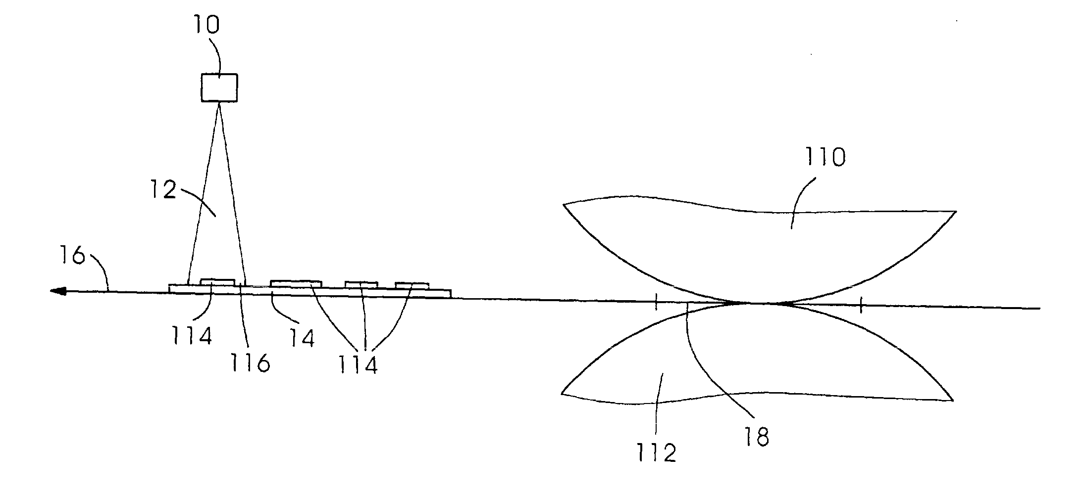
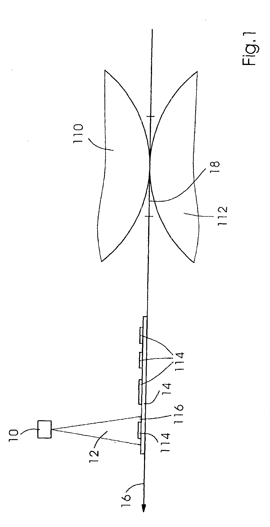
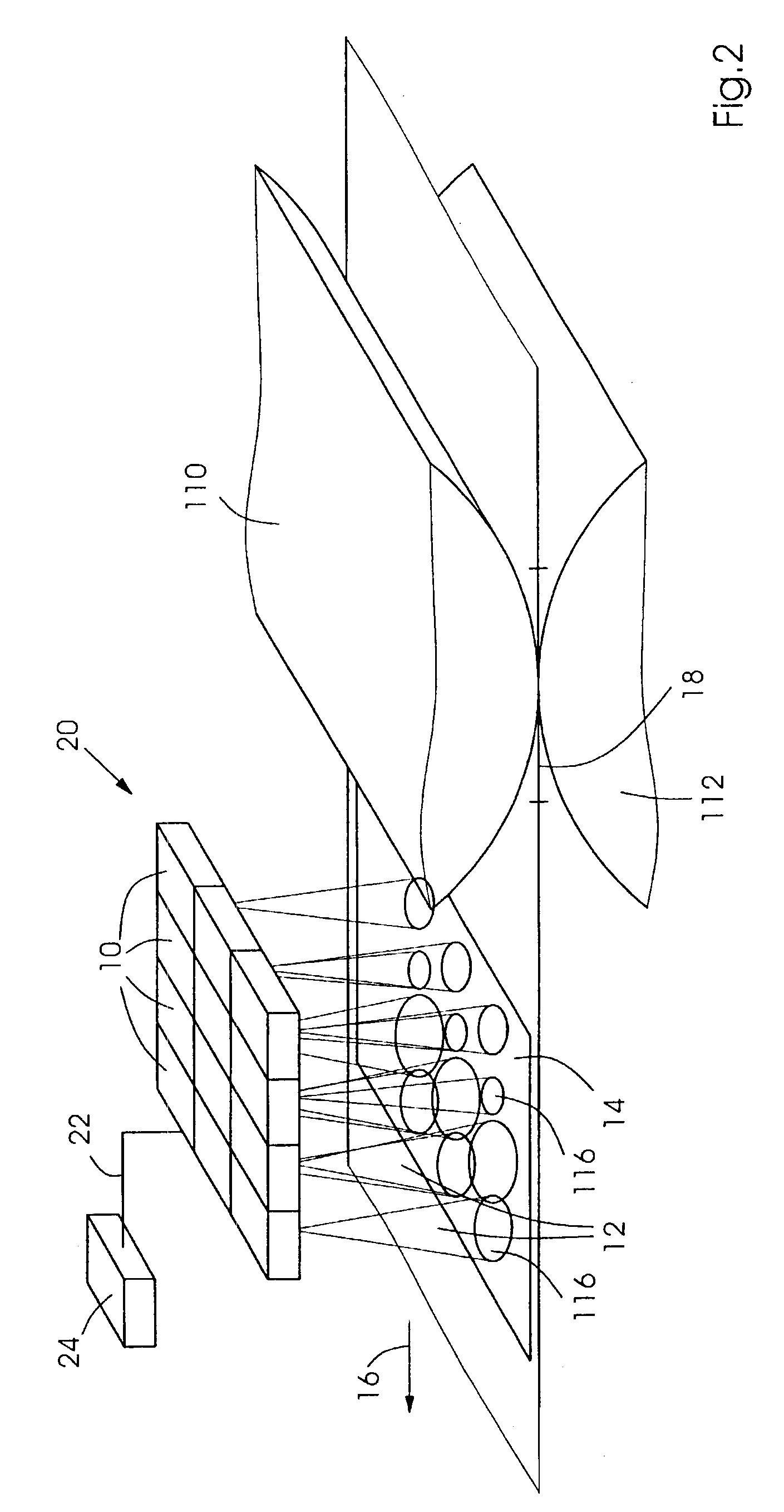
FIG. 1 shows a schematic representation to illustrate the arrangement of an embodiment of the present invention in a planographic printing press. A radiant energy source 10, in particular a laser, preferably a diode laser or solid laser, is arranged within a planographic printing press in such a manner that light 12 which is emitted by the radiant energy source impinges on a printing substrate 14 on its path 16 through the planographic printing press at a position 116 downstream of a printing nip 18. While in FIG. 1, printing substrate 14 is shown, by way of example, in sheet form, the printing substrate can also be passed through the planographic printing press in web form. The orientation of path 16 of printing substrate 14 is indicated by an arrow. Here, the path is shown to be linear without limitation of a generally curved or non-linear course, in particular, on a circular arc. In the embodiment shown in FIG. 1, printing nip 18 is defined by the interaction of printing cylinder...


PUM

PropertyMeasurementUnit
wavelengthaaaaaaaaaa

Abstract

A device for supplying radiant energy of a wavelength in the near infrared onto a printing substrate (14) in a planographic printing press, including at least one radiant energy source (10) whose light (12) impinges on the printing substrate (14) on the path (16) of the printing substrate (14) through the printing press at a position (116) downstream of at least one printing nip (18) in a printing unit is described which has the feature that the radiant energy source (10) emits light (12) only in a narrow band, the wavelength of the light being non-resonant to absorption wavelengths of water and preferably being between 700.00 nm and 2500.00 run. Also disclosed is a method for supplying radiant energy. By supplying energy in this frequency range while avoiding absorption resonances of water, an unwanted drying or unnecessary heating of the printing substrate are advantageously reduced while providing energy to the printing ink for its particular drying process. The input of the radiant energy into the printing ink is assisted by an infrared-absorbing agent which is added to the printing ink.

Description

Priority is claimed to German Patent Application No. DE 101 49 844.6, filed Oct. 10, 2001, and German Patent Application No. DE 102 34 076.5, filed Jul. 26, 2002 the entire disclosures of which are hereby incorporated by reference.BACKGROUND OF THE INVENTIONpresent invention relates to a device for supplying radiant energy of a wavelength in the near infrared onto a printing substrate in a planographic printing press, including at least one radiant energy source whose light impinges on the printing substrate on the path of the printing substrate through the printing press at a position downstream of at least one printing nip in a printing unit. Moreover, the present invention relates to a method for supplying radiant energy of a wavelength in the near infrared onto a printing substrate in a planographic printing press.Depending on the type of printing ink and the underlying particular drying process, printing machines, in particular, planographic printing presses such as lithographi...

Claims


Application Information

Patent Timeline
Patent Type & Authority Patents(United States)
IPC IPC(8): B41F23/00B41F23/04F26B3/00F26B3/30C09D11/02
CPCB41F23/0413F26B3/30C09D11/03B41F23/0486B41M7/009
Inventor PITZ, HEINER
Owner HEIDELBERGER DRUCKMASCHINEN AG
Learn More