Bulk fueled gasifiers

Inactive Publication Date: 2010-05-06
WEAVER LLOYD E
View PDF3 Cites 11 Cited by
  • Summary
  • Abstract
  • Description
  • Claims
  • Application Information

AI Technical Summary

Benefits of technology

[0010]FIG. 3 is a side elevation view of a non-

Problems solved by technology

This extra fuel preparation increases the cost and complexity of the gasifier and also lowers reliability.
Entrained flow gasifiers also tend to be very large and cumbersome, with present reliability so poor that two gasifiers are frequently supplied to do the job of one.
Bulk fuel fed gasifiers are generally simpler than entrained flow gasifiers, but they typically employ counter-current designs that tend to create undesirable tars.
Tars that are very undesirable to further process gas

Method used


Image

  • Bulk fueled gasifiers
  • Bulk fueled gasifiers
  • Bulk fueled gasifiers

Examples


Embodiment Construction

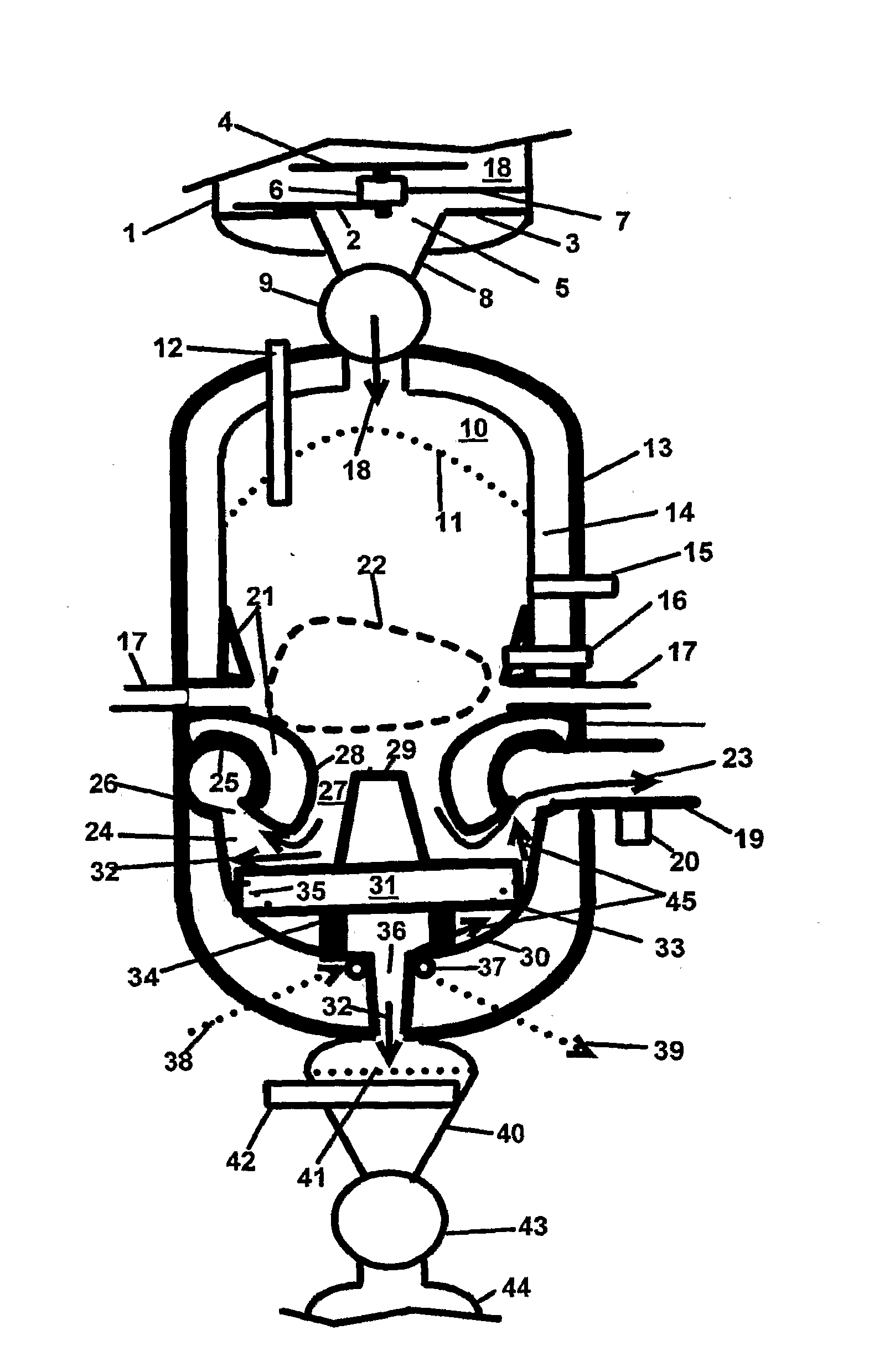
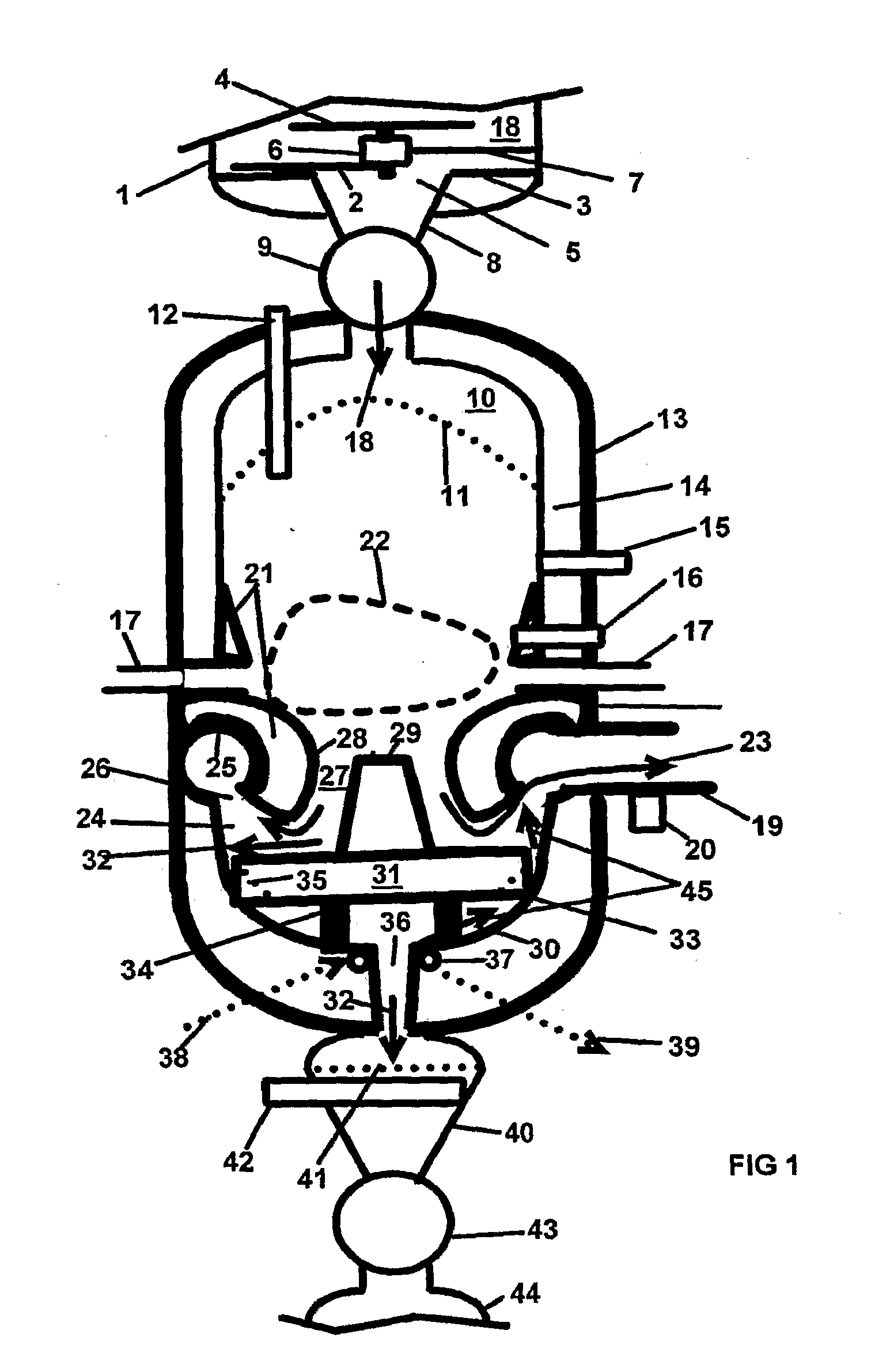
[0015]FIG. 1 shows one embodiment of a slagging gasifier as if it is being used in a pressurized operation, say up to thirty bar pressures. Valve details and controls for de-pressurizing and re-pressurizing lock hoppers and controls are well known and are not shown. The upper and body sections are described first and are the same for each ash discharge method.

[0016]Lock hopper 1 is filled using a conveyor (not shown) that has a much faster capacity than the maximum usage of the gasifier. Undercutting rotating inward helical front edge of self-aligning plate 2 performs the unloading function by pulling material from the outer perimeter of base 3 and under rotating cap 4. The loose spline drive connection of unloader plate 2 to drive motor 6 allows plate 2 to conform perfectly to base 3 when rotating, reducing friction and eliminating binding forces. Cap 4 prevents free fall of fuel or material 18 into unloader concentric opening 5. In conjunction with inward rotating helix plate 2, m...


PUM


Abstract

A gasifier includes a gasifier shell, means for introducing fuel into the shell, and means for introducing oxygenate into the shell. The gasifier also includes means for discharging gas from the shell, which can be located below the means for introducing oxygenate. The gasifier can also include means for re-circulating gas prior to gas being discharged from the shell.

Description

CROSS REFERENCES TO RELATED APPLICATIONS[0001]This application claims the benefit of U.S. Provisional Application No. 60 / 846,790, filed Sep. 22, 2008, U.S. Provisional Application No. 60 / 850,944, filed Oct. 11, 2008, and U.S. Provisional Application No. 60 / 875,483, filed Dec. 18, 2008.BACKGROUND OF THE INVENTION[0002]This invention relates generally to gasifiers. Two types of gasifiers are bulk fuel fed and entrained flow fed. Entrained flow fed gasifiers require more fuel processing such as pulverizers and slurring of coal, for example. Entrained flow also requires other extra equipment such as blowers and bag house. This extra fuel preparation increases the cost and complexity of the gasifier and also lowers reliability. Entrained flow gasifiers also tend to be very large and cumbersome, with present reliability so poor that two gasifiers are frequently supplied to do the job of one.[0003]Bulk fuel fed gasifiers are generally simpler than entrained flow gasifiers, but they typical...

Claims


Application Information

Patent Timeline
IPC IPC(8): C10J3/30
CPCC10J3/26C10J3/42F23G2209/261C10J2300/1823F23G2201/40C10J2200/15
Inventor WEAVER, LLOYD E.
Owner WEAVER LLOYD E
Why Eureka
Try Eureka