Image sensor

Active Publication Date: 2010-05-06
ARNOLD & RICHTER CINE TECHN & BETRIEBS
View PDF12 Cites 6 Cited by
  • Summary
  • Abstract
  • Description
  • Claims
  • Application Information

AI Technical Summary

Benefits of technology

[0011]It is the underlying object of the invention to provide an image sensor of the initially named kind with split

Problems solved by technology

As a rule, the individual column amplifiers cannot be manufactured completely identically with one another.
If, however, the mean value of the deviation over the upper column amplifier row deviates systematically from the mean value of the deviation over the lower column amplifier row, for example d

Method used


Image

  • Image sensor
  • Image sensor
  • Image sensor

Examples


Example

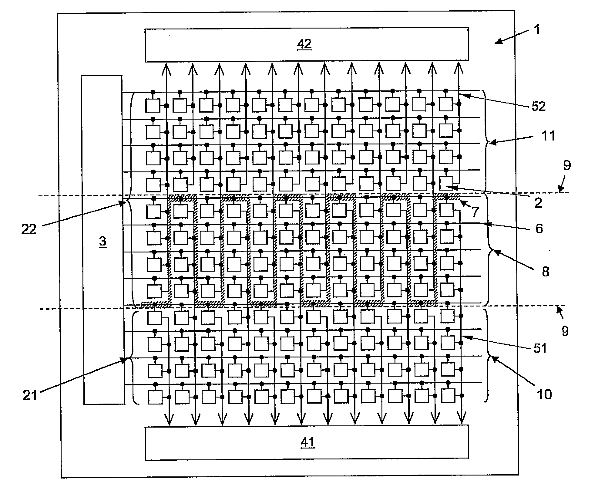
[0031]The CMOS image sensor 1 shown in FIG. 3 has a plurality of light-sensitive pixels 2 which are arranged in rows (shown horizontally here) and columns (shown vertically here). Each row has a row selection line 6 for the pixels 2 associated with the respective row. The image sensor 1 furthermore includes a row address logic 3 by which a respective one of the rows 6 can be selected for the reading out of the signals of the pixels 2 of this row 6.

[0032]The pixels of each column are in this respect divided into a lower pixel group 21 and an upper pixel group 22, with the division only being illustrated with reference numerals with reference to the column located at the left hand margin of the pixel field for reasons of simplicity in FIG. 3. The lower pixel group 21 of this singled out column includes four pixels 2; the upper pixel group 22 of this column includes eight pixels 2. The topmost pixel 2 of the respective lower pixel group 21 and the bottommost pixel 2 of the respective u...


PUM


Abstract

The invention relates to an image sensor, in particular to a CMOS image sensor, for electronic cameras, having a plurality of light-sensitive pixels arranged in rows and columns, wherein the pixels of a respective column are divided into a first pixel group and a second pixel group, wherein, in each column, the pixels of the respective first pixel group are coupled to a common first column amplifier via a common first column line and the pixels of the respective pixel group are coupled to a common second column amplifier via a common second column line. The division of the pixels into the first pixel group and second pixel group is different for different columns.

Description

CROSS-REFERENCE TO RELATED APPLICATION[0001]This application claims priority of German Patent Application No. 10 2008 052 916.8 filed Oct. 23, 2008, which is incorporated herein by reference.FIELD OF THE INVENTION[0002]The present invention relates to an image sensor, in particular to a CMOS image sensor, for electronic cameras, having a plurality of light-sensitive pixels arranged in rows and columns.BACKGROUND OF THE INVENTION[0003]Known electronic cameras include an image sensor which comprises a plurality of light-sensitive elements—so-called pixels—which are arranged in rows and columns and which convert light incident through an objective of the camera into electrical signals. Each of the pixels is addressed to read out an image, with each pixel corresponding to a respective picture element of the image. A signal which is proportional to a charge of the pixel collected by an exposure is conducted to an output of the image sensor.[0004]Sensors are in particular known which have...

Claims


Application Information

Patent Timeline
IPC IPC(8): H04N5/335
CPCH01L27/14643
Inventor CIESLINSKI, MICHAEL
Owner ARNOLD & RICHTER CINE TECHN & BETRIEBS
Why Eureka
Try Eureka