Laser projection system

Inactive Publication Date: 2010-05-06
YOUNG OPTICS
View PDF11 Cites 17 Cited by
  • Summary
  • Abstract
  • Description
  • Claims
  • Application Information

AI Technical Summary

Benefits of technology

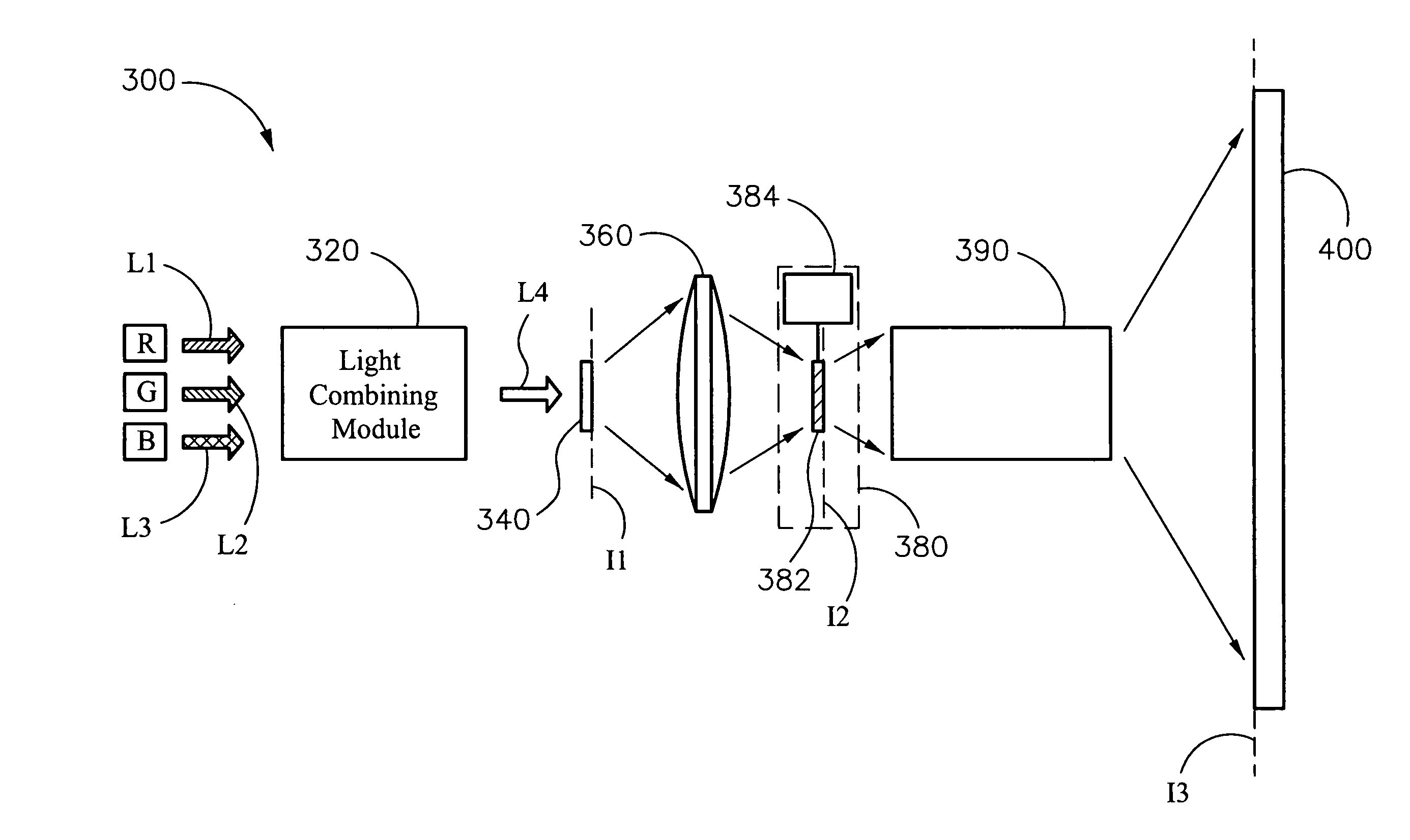
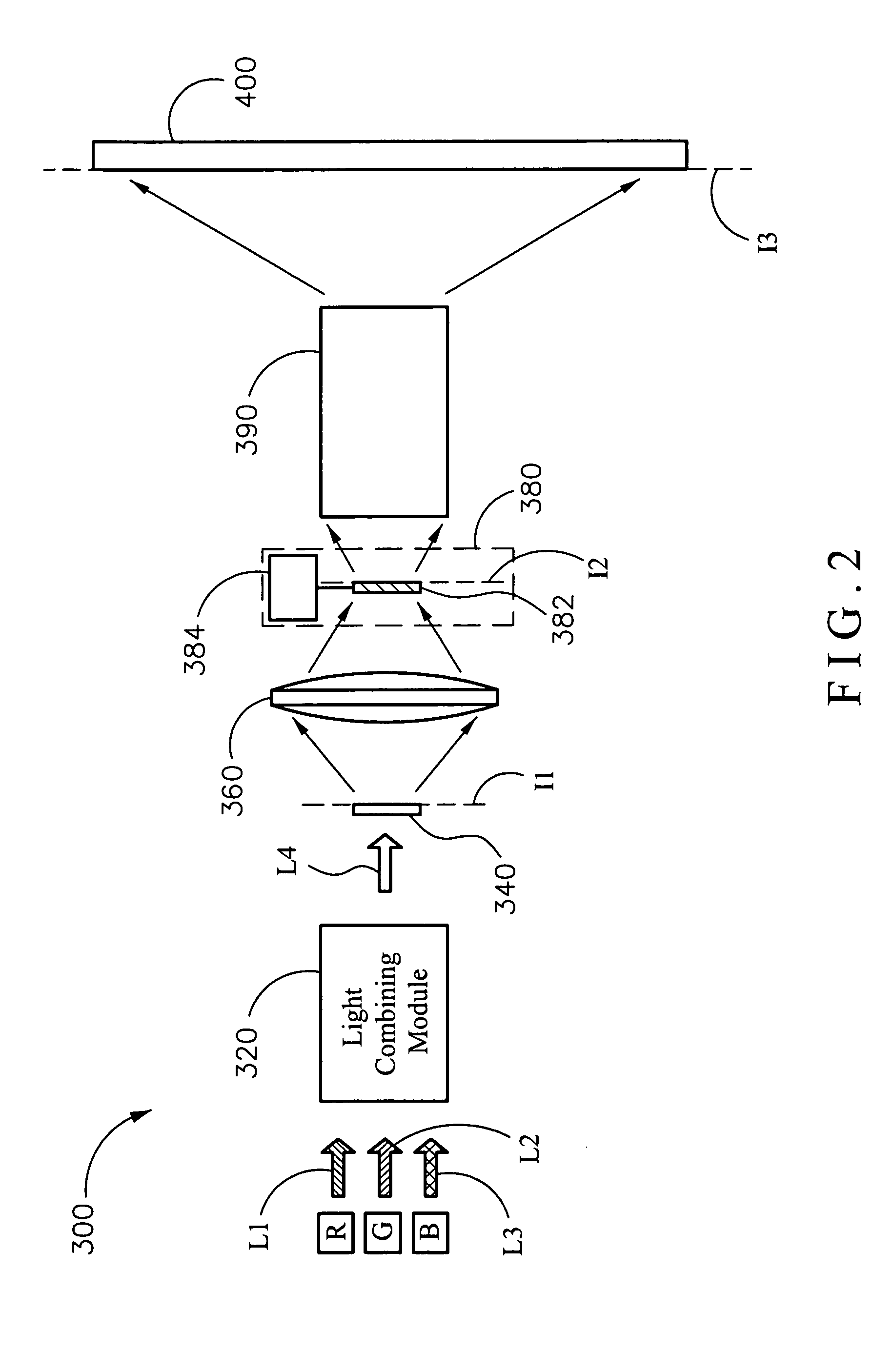
[0012]The present invention is to provide a laser projection system capable of improving the phenomenon of the laser speckles on the image.
[0019]The embodiments of the present invention uses the lens to focus the image formed by the image generating module on the moveable or rotatable diffuser, so as to corrupt the coherence of the laser light for further decreasing the laser speckle of the image.

Problems solved by technology

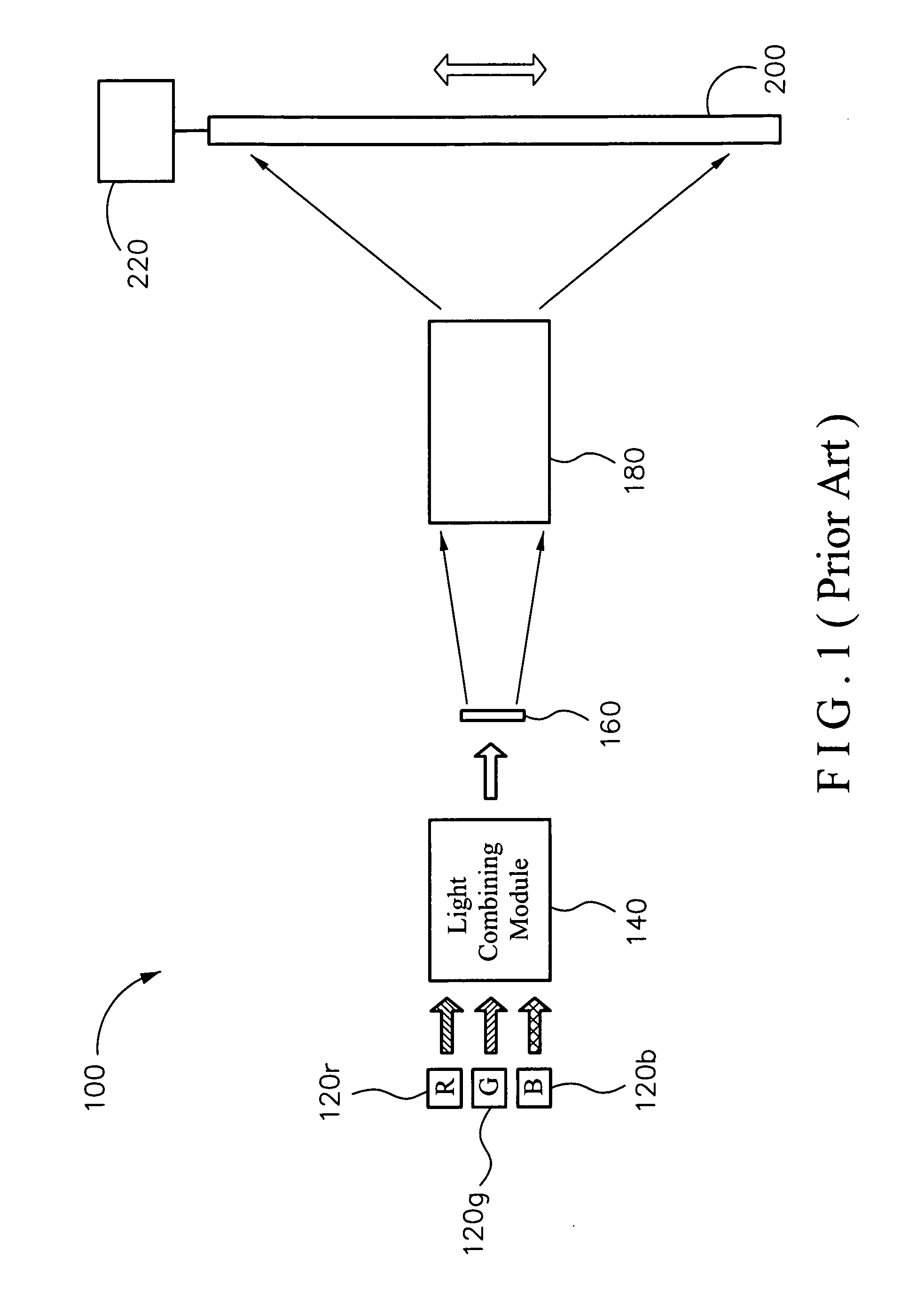
Conventional projectors use light emitting diodes (LEDs) as light sources but the photoelectric converting efficiency is limited.
However, when the laser is used as the light source of a projector, laser speckles appear.
The conventional screen 200 is very large, and the actuating mechanism 220 may be large enough to drive the screen 200, which is inconvenient in application and also has problems about noise and shock resistance in the product reliability test.

Method used


Image

  • Laser projection system
  • Laser projection system
  • Laser projection system

Examples


Embodiment Construction

[0028]In the following detailed description of the preferred embodiments, reference is made to the accompanying drawings which form a part hereof, and in which is shown by way of illustration specific embodiments in which the invention may be practiced. In this regard, directional terminology, such as “top,”“bottom,”“front,”“back,” etc., is used with reference to the orientation of the Figure(s) being described. The components of the present invention may be positioned in a number of different orientations. As such, the directional terminology is used for purposes of illustration and is in no to way limiting. On the other hand, the drawings are only schematic and the sizes of components may be exaggerated for clarity. It is to be understood that other embodiments may be utilized and structural changes may be made without departing from the scope of the present invention. Also, it is to be understood that the phraseology and terminology used herein are for the purpose of description ...


PUM


Abstract

A laser projection system includes a plurality of laser light sources, a light combining module, an image generating module, a lens, a diffusion module. and a projection lens. The laser light sources are used to provide a plurality of light beams with different colors. The light combining module is disposed in the light path of the laser beams for mixing the laser beams to form a mixing light beam. The image generating module is disposed in the light path of the mixing light beam for receiving the mixing light beam to generate a first image. The lens is disposed in the light path of the first image and provides an imaging position. The first image passes through the lens to form a second image at the imaging position. The diffusion module includes a diffuser and an actuator. The projection lens projects the second image on a screen.

Description

BACKGROUND OF THE INVENTION[0001](1) Field of the Invention[0002]The present invention relates to a projection system, and more particularly, to a projection system using a laser as a light source.[0003](2) Description of the Prior Art[0004]A projector is constituted of a light source, an illuminating module, an image generating module and so on. The illuminating module has an integration rod and a focusing lens, etc. The image generating module has a light engine and a projection lens, etc. The light beam is emitted from the light source and passes through the integration rod, the focusing lens, and the light engine to form an image beam, and then the image beam is projected on a screen through the projection lens to form an image. Generally, the light source may be a lamp, a light emitting diode (LED) or a laser light source. The projectors may be classified into liquid crystal panels, liquid crystal on silicon panels (LCOS panel), and digital micro-mirror devices (DMD).[0005]In r...

Claims


Application Information

Patent Timeline
IPC IPC(8): G03B21/14
CPCG03B21/14G03B21/2033G02B27/1033G02B27/141G02B27/48
Inventor LIAO, CHENG-SHUNCHENG, CHU-MINGCHEN, S-WEI
Owner YOUNG OPTICS
Why Eureka
Try Eureka