Method of determining properties of the earth

a technology of earth and properties, applied in seismology, seismology, instruments, etc., can solve the problem that the calculation of an iterative process requires significant computational resources

Inactive Publication Date: 2010-05-06
SCHLUMBERGER TECH CORP +1
View PDF11 Cites 16 Cited by
  • Summary
  • Abstract
  • Description
  • Claims
  • Application Information

AI Technical Summary

Benefits of technology

[0019]The preferred frequency range of signals processed in accordance with the invention are low pass or band filtered to restrict the frequency content of the signal to a range of 1 Hz to 50 Hz, more preferably 3 to 20 Hz and even more preferably 3 to 15 or even 10 Hz.
[0020]By combining local velocity-versus-depth data set information gained through the application of the invention with data obtained from the analysis of reflected seismic waves, the invention can be used to obtain a more general velocity model of the earth layers, including lateral variations. This model can then be applied in further seismic processing steps known per se to ultimately obtain an image of the location of reflectors within the subsurface of the earth.

Problems solved by technology

In 3D problems, the calculations for an iterative process require significant computational resources.

Method used


Image

  • Method of determining properties of the earth
  • Method of determining properties of the earth
  • Method of determining properties of the earth

Examples


Embodiment Construction

[0028]In the following description, for the purposes of explanation, the background technologies, a basic example of this invention and various preferred embodiments of the basic example are set forth in order to provide a thorough understanding of the invention. However, it will be apparent that the invention may be practiced without these specific details.

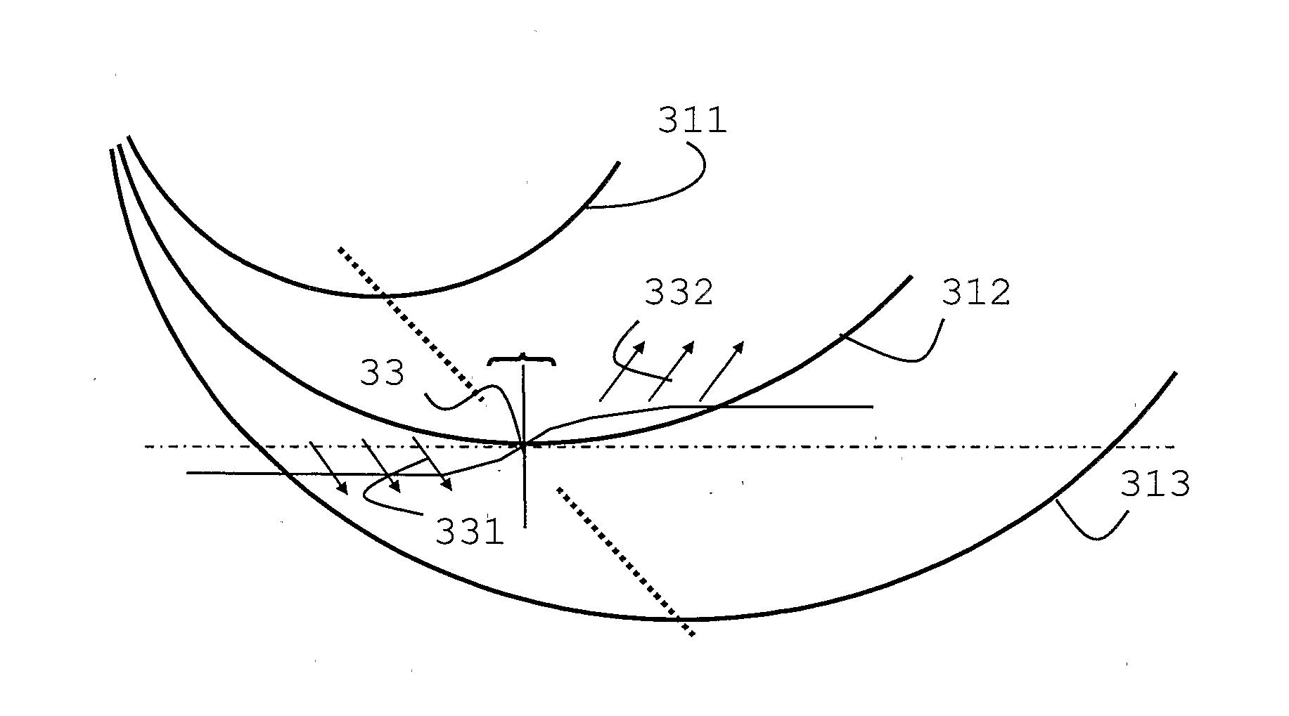
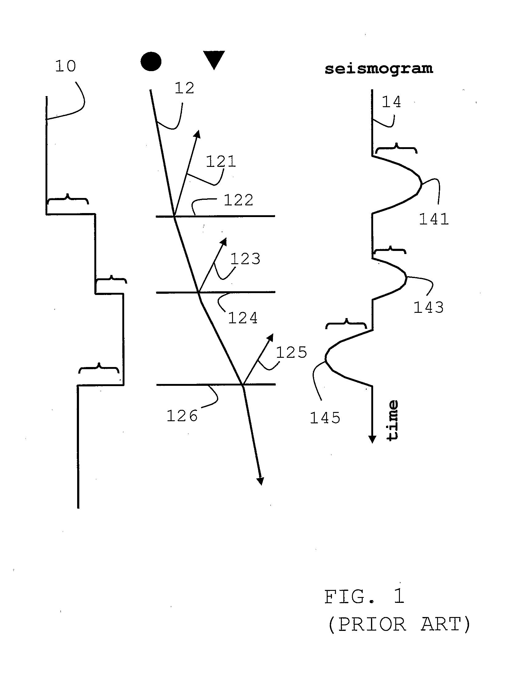
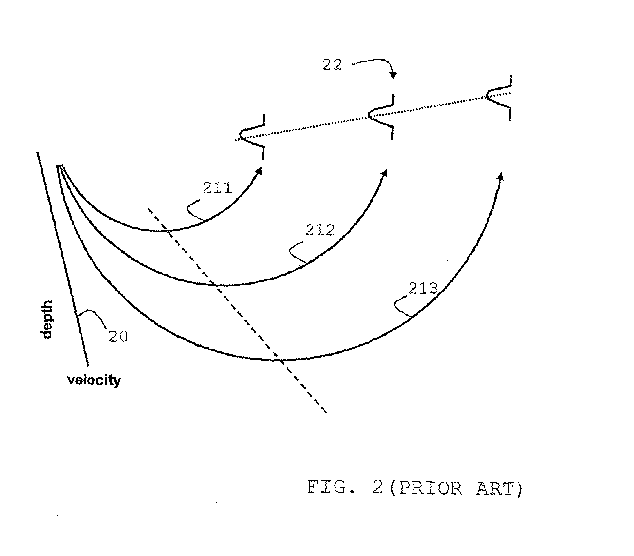
[0029]FIG. 1 and FIG. 2 show known properties of reflection and turning wave seismograms, respectively. Both simplified and schematic diagrams serve to illustrate key differences to the treatment of turning waves in accordance with the present invention, an example of which is shown in FIG. 3.

[0030]FIG. 1 has three parts, showing from left to right a velocity profile 10 with depth, a ray path 12 of a seismic signal with reflected parts 121, 123, 125 at each layer boundary 122, 124, 126 and a seismogram 14 as would be registered by a receiver on the surface.

[0031]The seismogram registers the two reflections 121, 123 at layers 122,...


PUM


Abstract

There is provided a method of direct waveform inversion of turning waves (311, 312, 313) to determine parameters characterizing properties of the earth or sub-sections of the earth, particularly of parts of the earth which are capable of trapping hydrocarbons with the inversion yielding from the wavefield of turning waves information representing or being equivalent to velocities or slownesses and/or the gradient of velocities or slownesses, particularly by evaluating wavefield data in the vicinity of turning points (33). The method can be applied sequentially as a survey sinking method.

Description

[0001]The present invention relates to methods of determining from seismic signals properties of the earth, particularly velocity or slowness of earth layers. It relates further to the use of turning wave signals within the seismic signals.BACKGROUND OF THE INVENTION[0002]The primary goal of seismic exploration is to obtain images of subsurface geological formations based upon information gleaned from recordings of a class of acoustic wave signals usually referred to as a seismic wavefield which is purposefully directed into the earth and recorded after having traveled through sections of the earth.[0003]The propagation of the seismic wavefield from the source to the receivers is dominated by geophysical properties of the layers through which the signals travel. The interpretation of the seismic wavefield yields in the first instance acoustic properties of the layers, the most important of which are known as elastic constants, which in turn can be used to determine other properties ...

Claims


Application Information

Patent Timeline
Patent Type & Authority Applications(United States)
IPC IPC(8): G01V1/38G01V1/30
CPCG01V1/303G01V1/30
Inventor THOMSON, COLIN
Owner SCHLUMBERGER TECH CORP
Why Eureka
Try Eureka