Drill for rapid dental implant

Inactive Publication Date: 2010-05-06
CHEN CHU LEON
View PDF11 Cites 40 Cited by
  • Summary
  • Abstract
  • Description
  • Claims
  • Application Information

AI Technical Summary

Benefits of technology

[0008]The present invention has been accomplished under the circumstances in view. It is therefore the main object of the present invention to provide a drill fo

Problems solved by technology

According to the aforesaid conventional cut hole drilling method, different sizes of drills must be used,

Method used


Image

  • Drill for rapid dental implant
  • Drill for rapid dental implant
  • Drill for rapid dental implant

Examples


Embodiment Construction

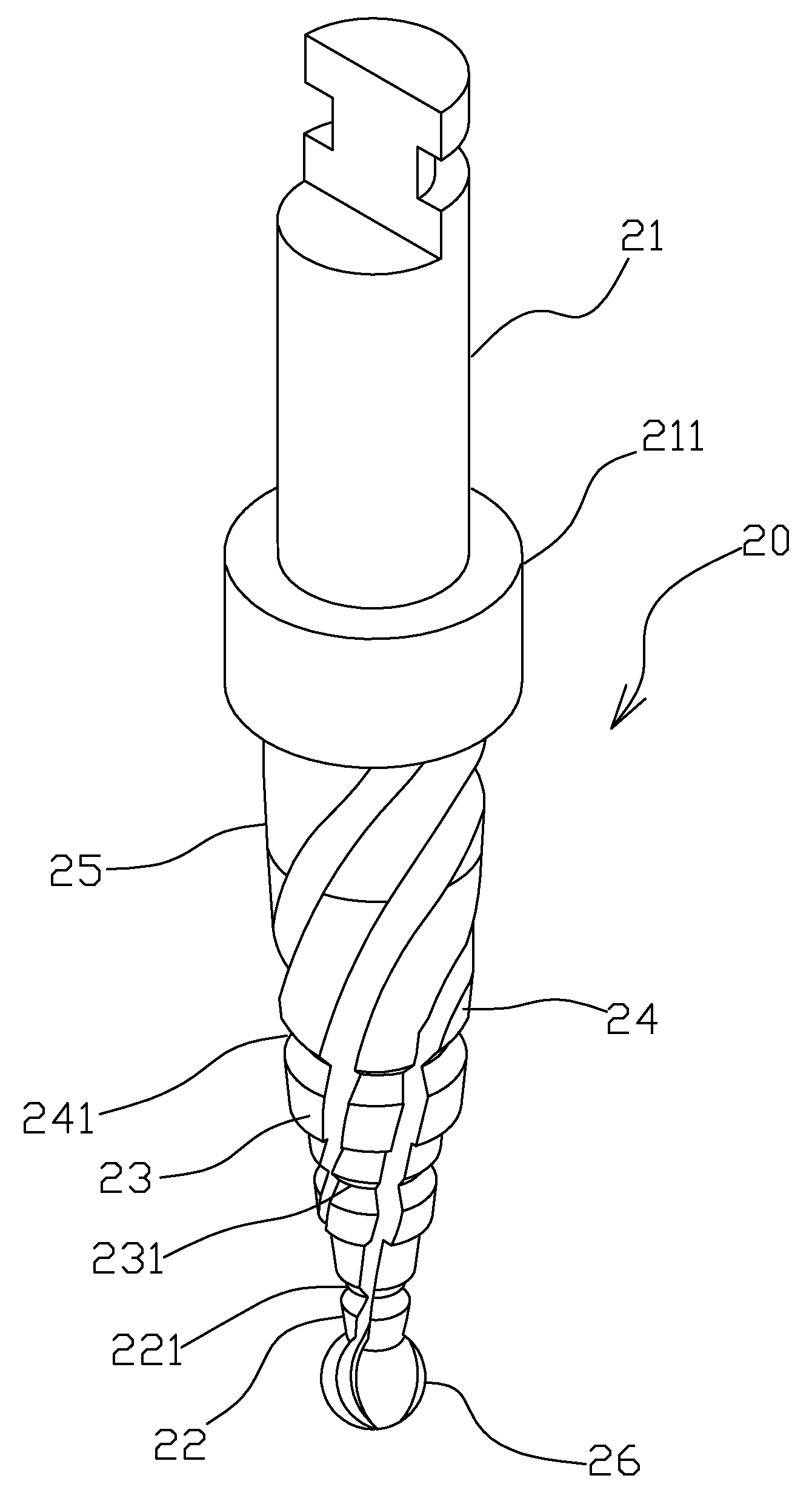
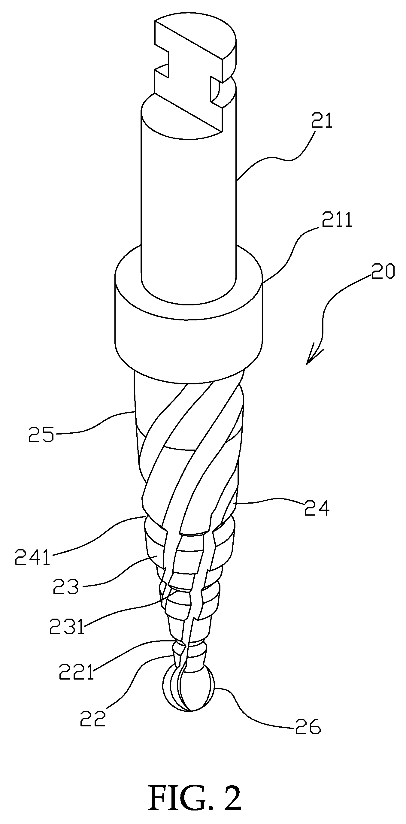
[0014]Referring to FIGS. 2 and 3, a drill 20 in accordance with the present invention is shown comprising a connection head 21 configured for quick connection to a dental handpiece, a stop block 211 disposed at the bottom side of the connection head 21, a round bur 26 disposed at the distal end, and a series of active drill body portions 22˜25 axially extending upwards from the round bur 26 to the bottom side of the stop block 211 in axial alignment with the connection head 21 in the order from the smallest diameter to the largest diameter in the direction from the round bur 26 toward the connection head 21. The round bur 26 is for location marking and crestal bone flattening. The active drill body portions 22˜25 are for drilling a vertical hole on the crown.

[0015]The active drill body portions 22˜24 show a conical configuration. A V-groove 221, 231 or 241 is provided around the periphery of the drill 20 between each two adjacent ones of the active drill body portions 22˜24 so that ...


PUM


Abstract

A drill for dental implant is disclosed to include a connection head configured for quick connection to a dental handpiece, a round bur, and a series of active drill body portions of different diameters connected between the connection head and the round bur, said active drill body portions in an order from the smallest diameter to the largest diameter in direction from the round bur toward the connection head.

Description

BACKGROUND OF THE INVENTION[0001]1. Field of the Invention[0002]The present invention relates to a drill dental implant and more particularly, to a high-efficient drill for drilling a hole on a crestal bone efficiently at a time for direct tapping.[0003]2. Description of the Related Art[0004]During dental implant placement, osteotomy is performed to make a proper size round hole on the crestal bone for the installation of an implant.[0005]During osteotomy, drills are used to drill a cut hole. According to conventional designs, different sizes of drills, as shown in FIG. 1 A˜J, are used to finish the drilling operation. In FIG. 1, the component referenced by A is a round bur for flattening the occlusal surface of the crestal bone 10 and making a location mark for implant; the components referenced by B, C, E, F, G and H are drills of different diameters for drilling a cut hole smaller than the diameter of the implant (for example, if the diameter of the implant is 4.75 mm, the diamet...

Claims


Application Information

Patent Timeline
IPC IPC(8): A61C3/02
CPCA61C3/02A61C8/0089
Inventor CHEN, CHU-LEON
Owner CHEN CHU LEON
Why Eureka
Try Eureka