
Optimal dispatch of demand side electricity resources

a technology of demand side and electricity resources, applied in the direction of electric devices, process and machine control, instruments, etc., can solve the problems of increasing subsequent load, many types of demand will actually consume more than their own, and the existing demand response program does not capture the impact of shifting/deferring load

Active Publication Date: 2010-05-06
GENERAL ELECTRIC CO
View PDF8 Cites 46 Cited by
  • Summary
  • Abstract
  • Description
  • Claims
  • Application Information

AI Technical Summary

Benefits of technology

[0015]Briefly, in accordance with one embodiment, a load dispatch system is configured to operate in response to algorithmic software to generate an optimized load dispa...

Problems solved by technology

Existing demand response programs do not capture the impact of shifting / deferring load from one time period to another.
In reality, however, many types of demand will actually consume more than their “normal” state following a curtailment event.
Delaying an industrial process on the other hand, will clearly result in an increase in subsequent load.
As demand response programs increase in size and more participation occurs via load shifting, the impacts of the rebound effect will result in greater efficiency losses, and the potential for secondary peaks being created.
This segment of load is relatively inelastic in the short term because it cannot be deferred.
Although the service provided by these loads depends on continuous power for a fixed period of time, the demand for the service itself is not instantaneous and often consumers may be indifferent to provision of the service within a range of time periods.
Although these appliances typically make up a small portion of the total residential load due to their intermittent usage, they do consume significant amounts of power while running and therefore offer the potential for significant peak shaving whenever they can be shifted to off peak consumption.
As such, consumers are indifferent to the actual time that this equipment runs, as long as the temperature remains within a certain range.
Core demand is instantaneous and inelastic.
Deferrable loads require power to provide their services, but the demand for those services is not instantaneous.
This presents the potential to defer the energy consumption in response to system conditions, such as price or contingencies.
Due to the nature of this type of demand, this will create a large potential for a rebound effect in subsequent hours after demand is dispatched.

Method used


Image

  • Optimal dispatch of demand side electricity resources
  • Optimal dispatch of demand side electricity resources
  • Optimal dispatch of demand side electricity resources

Examples


Embodiment Construction

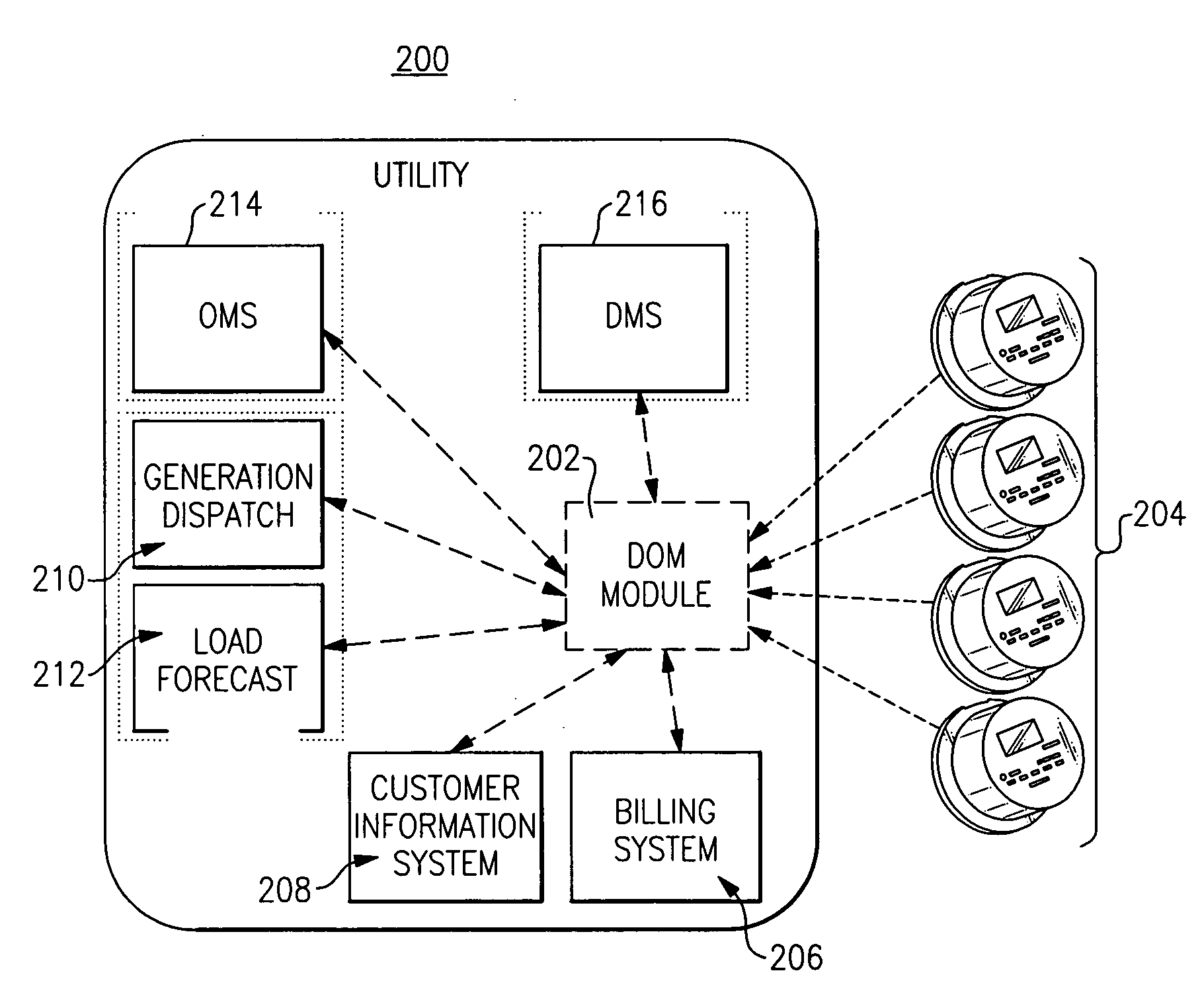
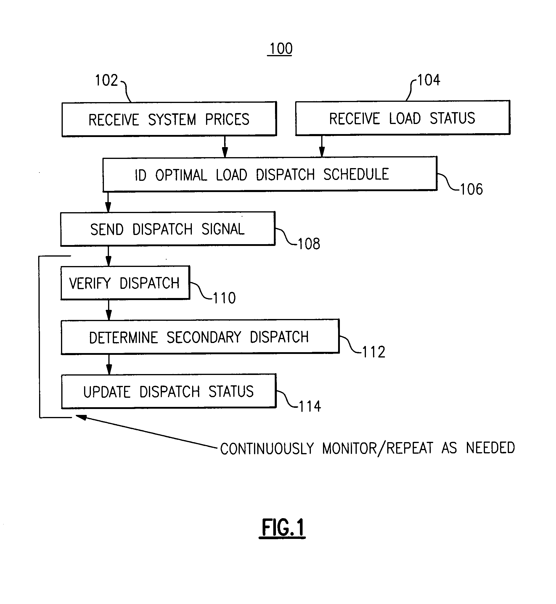
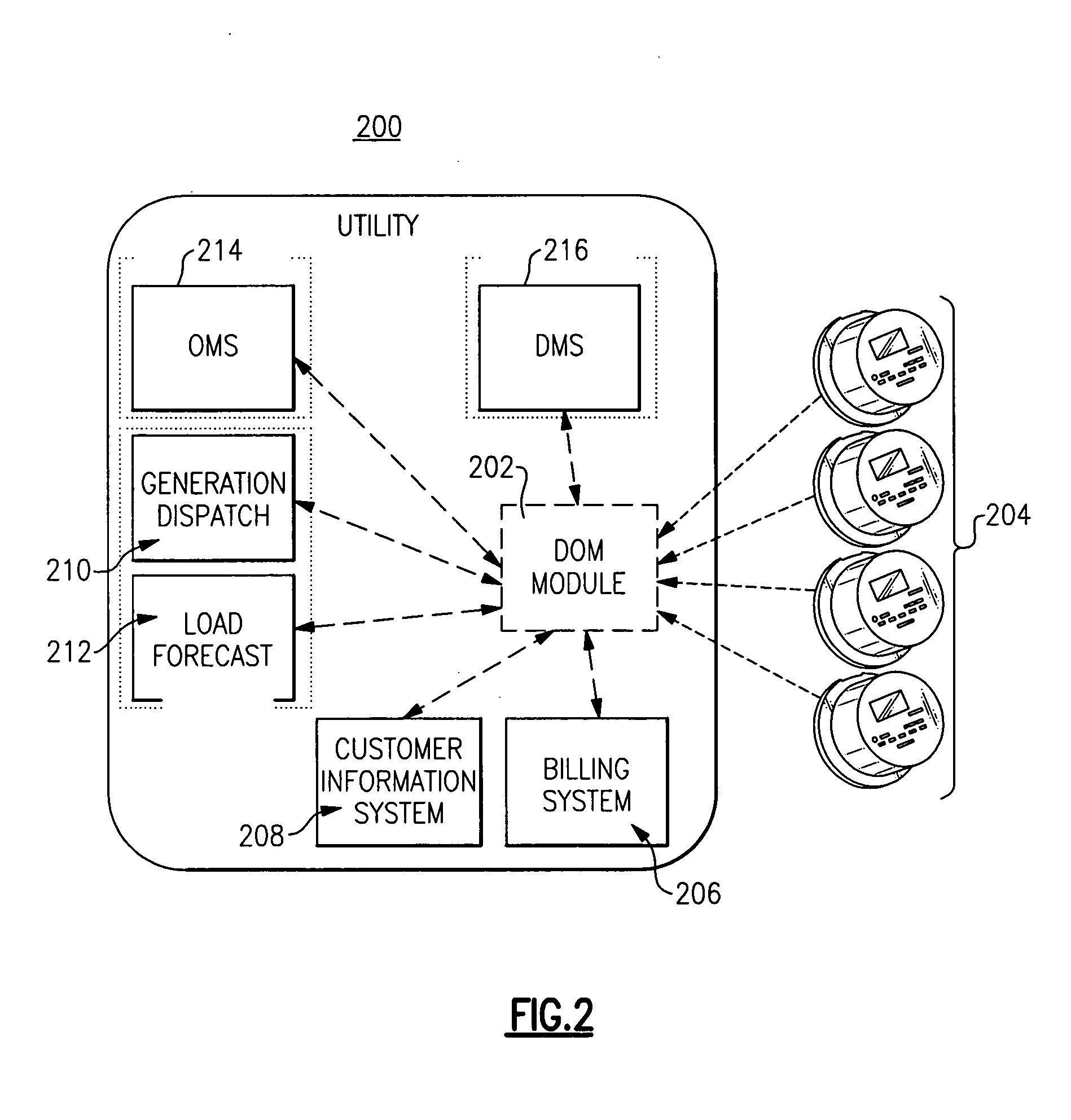
[0033]The embodiments described herein are directed to inclusion of the rebound effect when dispatching demand resources. Since the time scales for many demand response implementations are on the order of hours, once a demand resource ahs been dispatched, it is not only likely unavailable for re-dispatch during the same day, but it is also likely that the dispatched demand will actually increase in subsequent hours or time periods. A significant rebound component may thus contribute to demand response for load shifting applications such as those associated with air conditioning.

[0034]Further, many demand response programs offer contracts to participants that limit the number of demand response events, e.g. interruptions / curtailments or critical peak pricing events over a given time period, e.g. monthly, annual, etc. It may be necessary to compare the economic benefits associated with dispatch during the current period of interest versus the likelihood of achieving greater benefits i...


PUM


Abstract

A load dispatch system operates in response to algorithmic software to generate an optimized load dispatch schedule based on data selected from one or both of rebound effect data or optimized load dispatch schedule opportunity cost data corresponding to dispatching of resources with a contractually limited number of dispatches in a given time period.

Description

BACKGROUND[0001]The invention relates generally to demand side electricity resources, and more particularly to a method for integrating demand response into optimal dispatch algorithms for electric power systems.[0002]Existing demand response programs do not capture the impact of shifting / deferring load from one time period to another. When demand is dispatched, the load agrees to reduce consumption for the specified hour(s) according to the demand bid. Once the curtailment period expires, the current programs typically assume that the demand will then return to its “normal” or uncurtailed, baseline state (or at least fail to take the rebound effect into account). In reality, however, many types of demand will actually consume more than their “normal” state following a curtailment event. This increase in subsequent periods can be called a rebound effect.[0003]For deferred / shifted loads, consumption is delayed; and so it should be expected that subsequent periods will see an increase...

Claims


Application Information

Patent Timeline
IPC IPC(8): G06Q10/00G06F17/00
CPCG06Q50/06Y04S10/54G06Q10/06G06Q10/04
Inventor BLACK, JASON WAYNELARSON, RONALD RAYTYAGI, RAJESH
Owner GENERAL ELECTRIC CO
Learn More