Non-uniform cache architecture (NUCA)

a cache architecture and non-uniform technology, applied in the field of data storage, can solve the problems of high latency and storage inefficiency

Inactive Publication Date: 2010-05-06
IBM CORP
View PDF18 Cites 71 Cited by
  • Summary
  • Abstract
  • Description
  • Claims
  • Application Information

AI Technical Summary

Problems solved by technology

Conventional “deep” cache hierarchies are characterized by significant cache management overhead (e.g., to manage coherency across all levels of the hierarchy), high latency access to lower levels of the cache hierarchy, and storage inefficiency in that a single multi-leve...

Method used


Image

  • Non-uniform cache architecture (NUCA)
  • Non-uniform cache architecture (NUCA)
  • Non-uniform cache architecture (NUCA)

Examples


Embodiment Construction

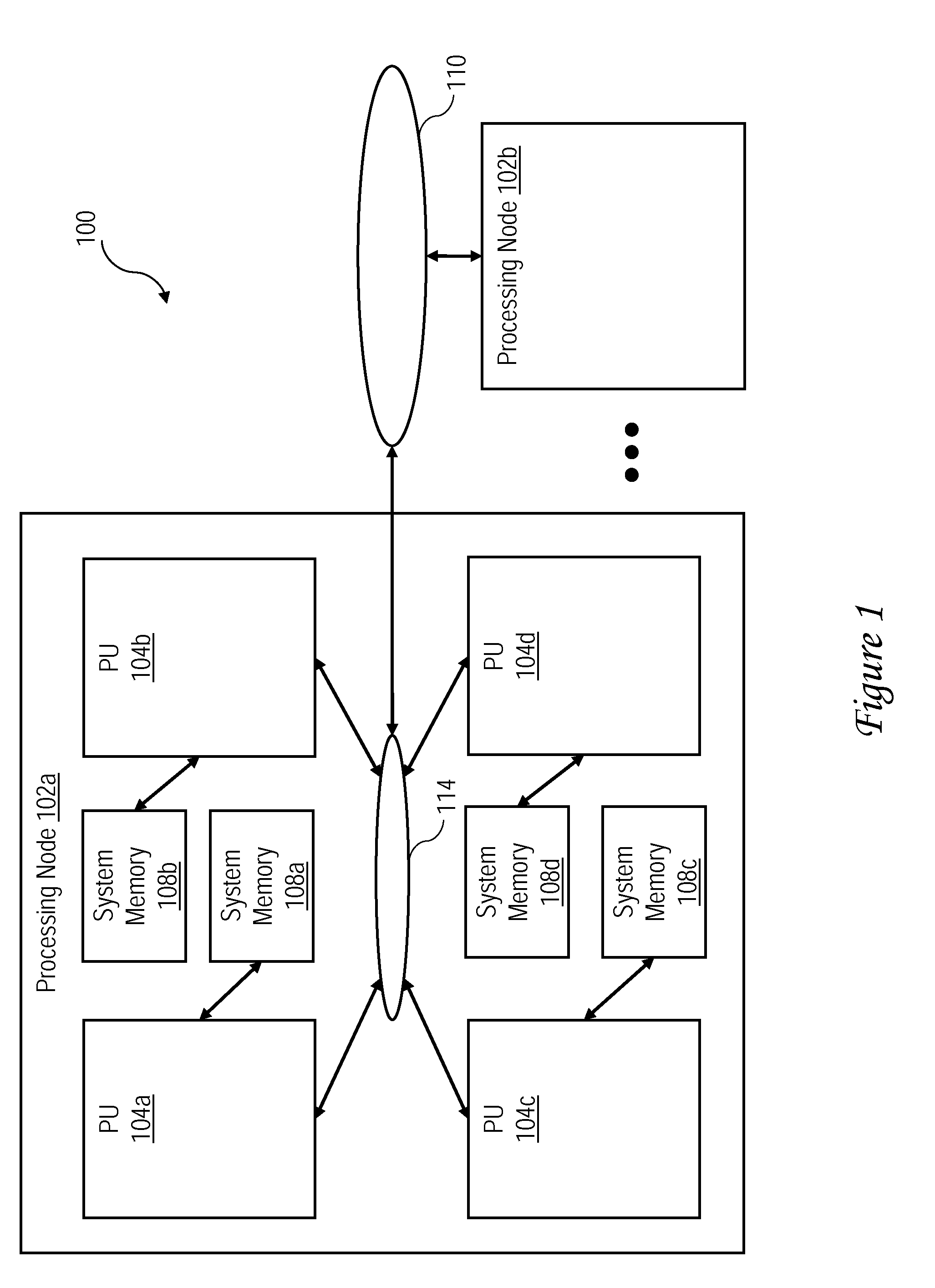
[0017]With reference now to the figures and, in particular, with reference to FIG. 1, there is illustrated a high level block diagram of an exemplary embodiment of a multiprocessor data processing system employing NUCA. As shown, data processing system 100 includes one or more processing nodes 102 (in this case, at least processing nodes 102a and 102b) for processing data and instructions. Processing nodes 102a, 102b are coupled to a system interconnect 110 for conveying address, data and control information. System interconnect 110 may be implemented, for example, as a bused interconnect, a switched interconnect or a hybrid interconnect.

[0018]In the depicted embodiment, each processing node 102 is realized as a multi-chip module (MCM) containing four processing units 104a-104d, each preferably realized as a respective integrated circuit. The processing units 104a-104d within each processing node 102 are coupled for communication by a local interconnect 114, which, like system inter...


PUM


Abstract

In one embodiment, a cache memory includes a cache array including a plurality of entries for caching cache lines of data, where the plurality of entries are distributed between a first region implemented in a first memory technology and a second region implemented in a second memory technology. The cache memory further includes a cache directory of the contents of the cache array and a cache controller that controls operation of the cache memory.

Description

[0001]This invention was made with Government support under DARPA, PERCS Phase III. THE GOVERNMENT HAS CERTAIN RIGHTS IN THIS INVENTION.BACKGROUND OF THE INVENTION[0002]1. Technical Field[0003]The present invention relates in general to data storage, and in particular, to a cache memory having a non-uniform cache architecture (NUCA).[0004]2. Description of the Related Art[0005]A conventional multiprocessor computer system includes multiple processing units all coupled to a system interconnect. Coupled to the system interconnect is a system memory, which represents the lowest level of volatile memory in the multiprocessor computer system and is generally is accessible for read and write access by all processing units. In order to reduce access latency to instructions and data residing in the system memory, each processing unit is typically further supported by a respective multi-level cache hierarchy for temporarily storing instructions and data retrieved from the system memory.[0006...

Claims


Application Information

Patent Timeline
IPC IPC(8): G06F12/08
CPCG06F12/0811G06F12/0846G06F12/0897G06F12/123G06F2212/225G06F2212/271G06F12/0848
Inventor LI, JIANRAJAMONY, RAMAKRISHNANSPEIGHT, WILLIAM E.WU, XIAOXIAZHANG, LIXIN
Owner IBM CORP
Why Eureka
Try Eureka