Pneumatic Tire

a pneumatic tire and tire body technology, applied in the field of pneumatic tires, can solve the problems of insufficient turning performance, insufficient ground area, and short edge effect in the lateral direction at the time of cornering, etc., to suppress the rigidity reduction of the block, suppress the toe and heel wear, and improve the effect of braking performan

Active Publication Date: 2010-05-13
TOYO TIRE & RUBBER CO LTD
View PDF8 Cites 36 Cited by
  • Summary
  • Abstract
  • Description
  • Claims
  • Application Information

AI Technical Summary

Benefits of technology

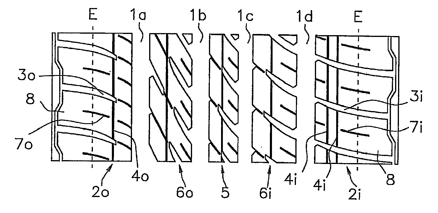
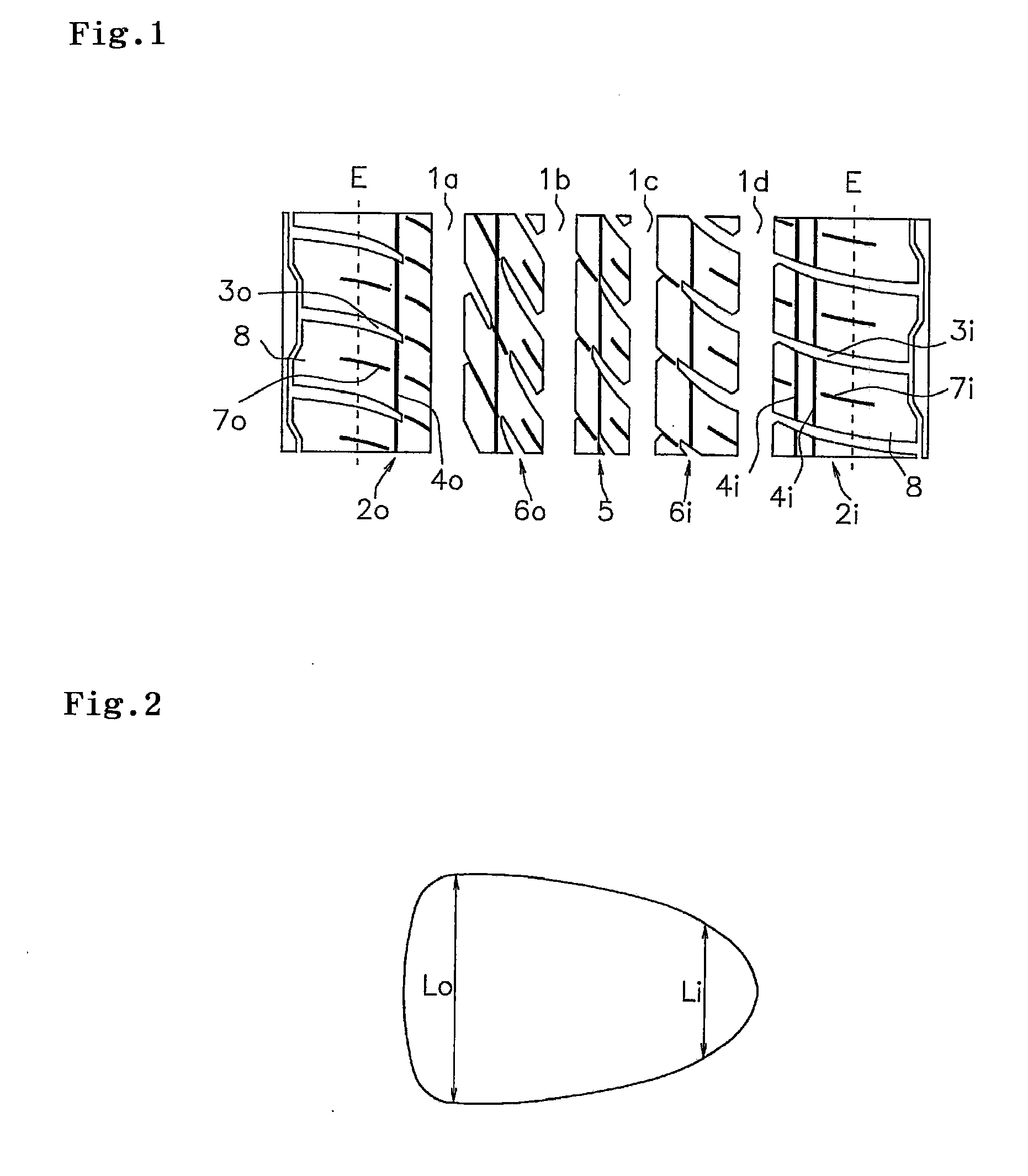
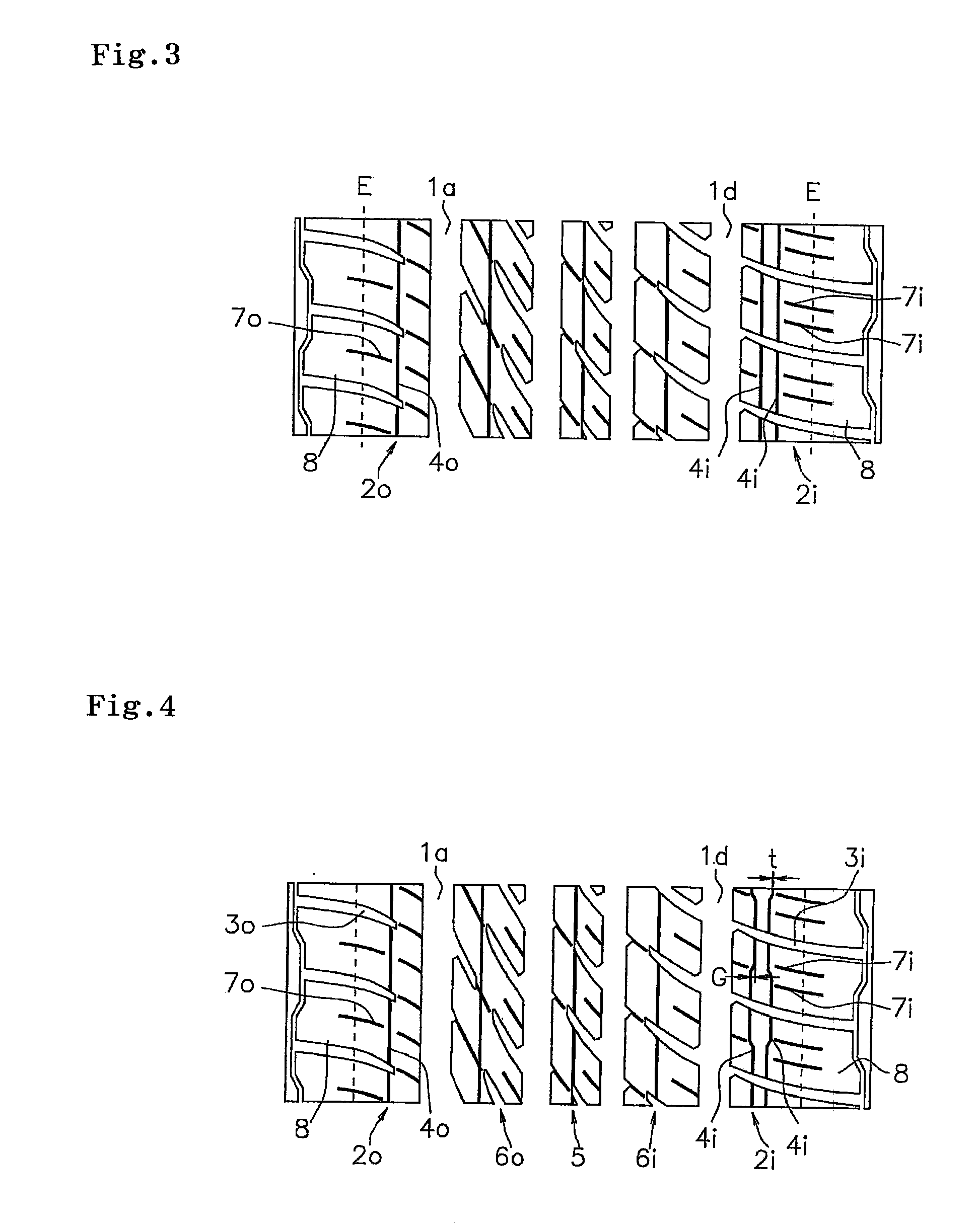
[0017]Accordingly, since the engaging action between the wall surfaces in the sipes in the width direction becomes larger in the vehicle inner side than in the vehicle outer side, it is possible to suppress the rigidity reduction of the block constructing the shoulder land portion in the vehicle inner side so as to achieve a more excellent braking performance, and it is possible to suppress a toe and heel wear with respect to the sipes in the width direction provided in the block.

Problems solved by technology

However, as a result of research work of the present inventor, it is known that there is a tendency that a ground area cannot be sufficiently obtained in the vehicle inner side at a time of cornering according to the structure mentioned above, and there is room for improvement of the turning performance.
In the structure mentioned above, since the circumferential sipe is not formed in the vehicle outer side, there is a problem that the edge effect in the lateral direction at a time of cornering tends to come short and the turning performance becomes insufficient.
However, this tire structure is provided for improving a snow steering stability, and does not suggest any solving means for securing the ground area in the vehicle inner side at a time of cornering, and further for enhancing the turning performance.

Method used


Image

  • Pneumatic Tire
  • Pneumatic Tire
  • Pneumatic Tire

Examples


example

[0042]An example tire which concretely shows the structure and effect of the present invention will be explained. An evaluation of each of performances is executed as follows.

[0043](1) Turning Performance

[0044]A cornering travel was carried out on a dry road surface, and a subjective evaluation was carried out according to a feeling test. An evaluation is shown by an index number in the case of setting a comparative example 1 to 100, and indicates that the larger the numerical value is, the better the turning performance is.

[0045](2) Braking Performance

[0046]A braking travel was carried out on a wet road surface, and a subjective evaluation was carried out according to a feeling test. An evaluation is shown by an index number in the case of setting a comparative example 1 to 100, and indicates that the larger the numerical value is, the better the braking performance is.

[0047](3) Ride Comfort

[0048]A travel was carried out on a general road surface, and a subjective evaluation was ca...


PUM


Abstract

A pneumatic tire has a tread pattern including a plurality of main grooves extending along a tire circumferential direction, and a shoulder land portion constructed by a rib or a block row formed in an outer side in a tire width direction of the main groove positioned in an outermost side. A circumferential sipe is provided in each of the shoulder land portions in both sides in the tire width direction. The number of the circumferential sipes provided in the shoulder land portion in a vehicle inner side is larger than the number of the circumferential sipes provided in the shoulder land portion in a vehicle outer side.

Description

BACKGROUND OF THE INVENTION[0001]1. Field of the Invention[0002]The present invention relates to a pneumatic tire having a tread pattern including a plurality of main grooves extending along a tire circumferential direction, and a shoulder land portion constructed by a rib or block row.[0003]2. Description of the Related Art[0004]Various tread patterns are formed in a tread surface of a pneumatic tire in correspondence to a demanded tire performance and a used condition. Since there is a case that a cut called a sipe is formed in a land portion of the tread surface, and it is possible to seize on a road surface based on an edge effect of the sipe, it is possible to enhance a turning performance at a time of cornering and a braking performance at a time of braking, even on a wet road surface and a dry road surface, in addition to an ice and snow road surface.[0005]Japanese Unexamined Patent Publication No. 2007-153104 describes a pneumatic tire in which a circumferential sipe is prov...

Claims


Application Information

Patent Timeline
Patent Type & Authority Applications(United States)
IPC IPC(8): B60C11/01
CPCB60C11/0306B60C11/0332B60C11/12B60C11/1218B60C11/1263B60C2011/1209B60C2011/1295
Inventor MIYAZAKI, TETSUJI
Owner TOYO TIRE & RUBBER CO LTD
Why Eureka
Try Eureka