Method and apparatus for visualizing a quantity of a material used in a physical object having a plurality of physical elements

a technology of physical objects and quantities, applied in the direction of 2d-image generation, static indicating devices, instruments, etc., can solve the problems of difficult selection of each and every element made of concrete, long and arduous tasks, and enormous complexity of building design projects

Active Publication Date: 2010-05-13
AUTODESK INC
View PDF10 Cites 29 Cited by
  • Summary
  • Abstract
  • Description
  • Claims
  • Application Information

AI Technical Summary

Benefits of technology

[0038]FIG. 6 is a diagram of an illustrative example of the data category user interface 500 following selection of a feature. In the illustrated embodiment, the feature is selected by dragging the second graphic feature 504B representing the percentage of recycled material content for ...

Problems solved by technology

Typically, the use of such programs involves a complex series of user commands to define or select system parameters that are used in the design.
By their very nature, design projects associated with buildings can be enormously complex.
The problem i...

Method used


Image

  • Method and apparatus for visualizing a quantity of a material used in a physical object having a plurality of physical elements
  • Method and apparatus for visualizing a quantity of a material used in a physical object having a plurality of physical elements
  • Method and apparatus for visualizing a quantity of a material used in a physical object having a plurality of physical elements

Examples


Embodiment Construction

[0022]In the following description, reference is made to the accompanying drawings which form a part hereof, and which is shown, by way of illustration, several embodiments of the present invention. It is understood that other embodiments may be utilized and structural changes may be made without departing from the scope of the present invention.

Hardware Environment

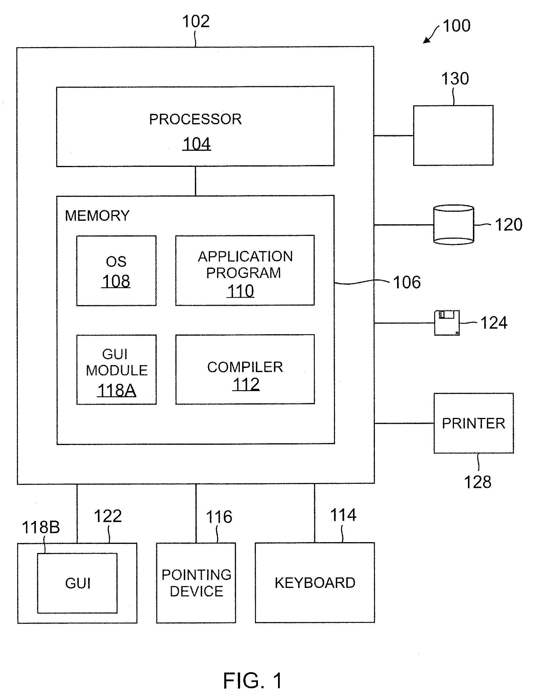
[0023]FIG. 1 illustrates an exemplary computer system 100 that could be used to implement the present invention. The computer 102 comprises a processor 104 and a memory, such as random access memory (RAM) 106. The computer 102 is operatively coupled to a display 122, which presents images such as windows to the user on a graphical user interface 118B. The computer 102 may be coupled to other devices, such as a keyboard 114, a mouse device 116, a printer, etc. Of course, those skilled in the art will recognize that any combination of the above components, or any number of different components, peripherals, and other device...


PUM


Abstract

A method, apparatus, article of manufacture for illustrating progress in achieving a goal of a system modeled by a computer program. In one embodiment, the invention is evidenced by a method comprising the steps of displaying a widget wherein the widget comprises a center portion representing a category of data represented by the computer program and the category of data includes n data points that must be fulfilled to achieve the goal and an outer portion, comprising a segment representing each one of the n data points; and updating the widget to represent each of the n data points that has been fulfilled by delineating each segment representing a fulfilled data point requirement from each segment representing a non-fulfilled data point requirement.

Description

BACKGROUND OF THE INVENTION[0001]1. Field of the Invention[0002]The present invention relates to systems and methods for providing information to users of computer programs, and in particular to a method and apparatus for visualizing a quantity of material used in a physical object modeled on a computer.[0003]2. Description of the Related Art[0004]Computer programs have long been used to assist users in the completion of a wide variety of projects. Examples of such computer programs include computer-aided design (CAD) and computer aided manufacture (CAM) programs. Typically, the use of such programs involves a complex series of user commands to define or select system parameters that are used in the design. Often times, the goal of the design process is to define a system that maximizes (or minimizes) certain criteria based on the selection of design parameters. Such parameters may be defined by the user or imposed upon the user by regulatory agencies or customers. One example of a ...

Claims


Application Information

Patent Timeline
IPC IPC(8): G06T15/00
CPCG06Q50/04G06T11/206G06Q50/08Y02P90/30
Inventor DEMCHAK, GREGORY L.SMITH, LILLIAN M.
Owner AUTODESK INC
Why Eureka
Try Eureka