
Electrical connecting device

Active Publication Date: 2010-05-13
YAMAICHI ELECTRONICS
View PDF46 Cites 14 Cited by
  • Summary
  • Abstract
  • Description
  • Claims
  • Application Information

AI Technical Summary

Benefits of technology

[0017]The invention has the above construction to enable stably holding the contacts in posture with a simple construction. Also, it is possible to readily adjust contact pressures between the contacts and two contacted articles independently. Moreover, a sliding magnitude can be readily adjusted. From the above matters, wiping between contact portions of the contacts and contacted articles can be surely performed. Accordingly, contact between these elements can be surely maintained and contact pressures can be made stable. Therefore, it is possible to maintain stable, electric connection between two contacted articles.
[0018]Also, by causing the elastic member to hold the contacts, the assembly can be unitized whereby exchange of a contact or the like can be made readily.

Problems solved by technology

Accordingly, it is difficult to support a plurality of contacts steadily in posture before contact with contacted articles, and, in particular, it is difficult to steadily hold a position of the tip-end contact portion of the upper contact piece whereby contact between the tip-end contact portion of the upper contact piece and a semiconductor device as a contacted article is not stable.
However, in view of the construction of the conventional, electrical connecting device, it is difficult to independently adjust contact pressures between the contact pieces of the contact and contacted articles and sliding magnitudes of the contact pieces.
Accordingly, for example, when a contact pressure between the tip-end contact portion of the upper contact piece and a contacted article is adjusted, there is a fear that a contact pressure between the tip-end contact portion of the lower contact piece and the contacted article changes and so a desired contact pressure cannot be obtained.
Further, in case of exchanging these contact and elastic member, the work of separately removing and separately mounting the contact and the elastic member is needed to make the exchanging work complex since the contact and the elastic member are separately supported.

Method used


Image

  • Electrical connecting device
  • Electrical connecting device
  • Electrical connecting device

Examples


Embodiment Construction

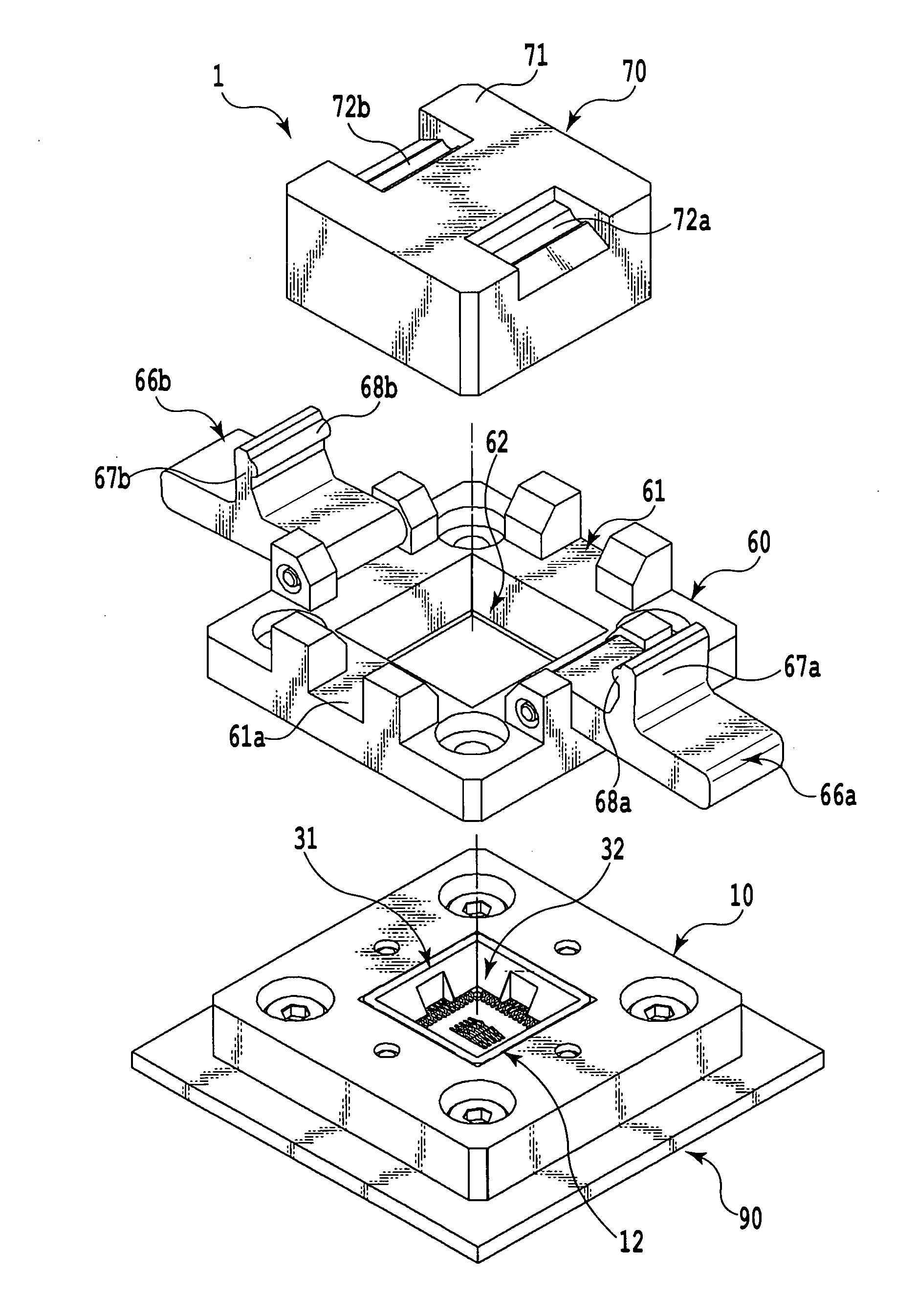
[0052]Embodiments of the invention will be described with reference to the drawings.

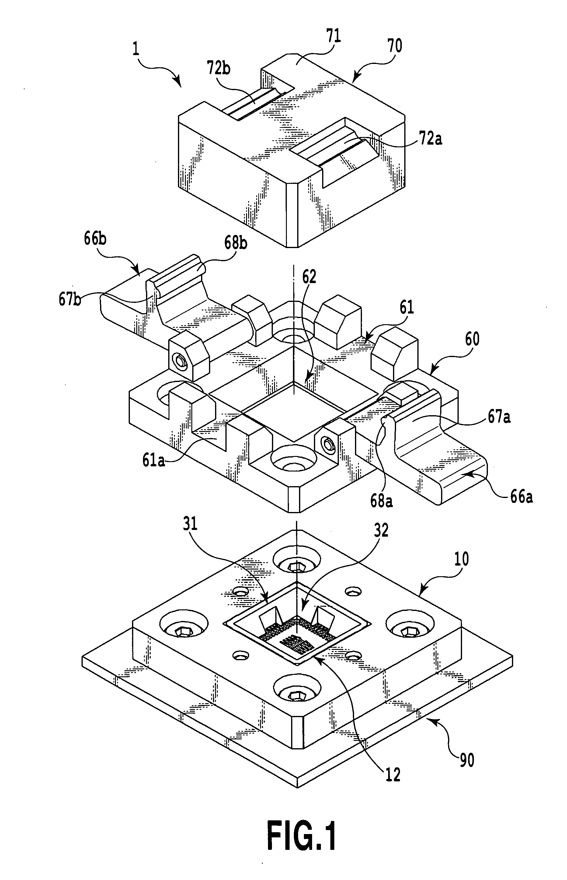
[0053]FIG. 1 is an exploded, perspective view showing the whole of an electrical connecting device according to a first embodiment of the invention, FIG. 2 is a partially enlarged, perspective view showing the electrical connecting device and including a cross sectional diagram, and FIG. 3A is a partially enlarged, perspective view showing a base member, which forms the electrical connecting device of FIG. 1, and including a cross sectional diagram showing an upper base member, which forms the base member. FIG. 3B is a partially enlarged, perspective view showing a base member, which forms the electrical connecting device of FIG. 1, and including a cross sectional diagram showing a lower base member, which forms the base member. FIG. 4 is a partially enlarged, perspective view including a cross sectional diagram showing an elastic member, which forms the electrical connecting device of FIG. 1. FIG. 5...


PUM


Abstract

An electrical connecting device for electrically connecting between two contacted articles, comprising a push member, a lock member, which holds one of the contacted articles in a predetermined mount position through the push member, a base member, to which the two contacted articles are mounted, an elastic member held on the base member, and a plurality of contacts held on the elastic member, and wherein the base member includes an upper base member and a lower base member, each including an accommodating recess, which accommodates the elastic member, the elastic member includes slits, respectively, holding the plurality of contacts, the plurality of contacts, respectively, include at least an upper contact arm having an upper contact portion and a lower contact arm having a lower contact portion, and the upper and lower contact portions of each of the plurality of contacts are structured to enable abutting against the elastic member.

Description

CROSS-REFERENCE TO RELATED APPLICATIONS[0001]This application claims the benefit of Japanese Patent Application No. 2008-289872, filed Nov. 12, 2008, which is hereby incorporated by reference herein in its entirety.BACKGROUND OF THE INVENTION[0002]1. Field of the Invention[0003]The present invention relates to an electrical connecting device for high frequency, and more particular, to an electrical connecting device, such as a semiconductor inspection socket, for electric connection of a semiconductor device for communication of high frequency signals and a circuit board, the electrical connecting device unitizing an elastic member and contacts so as to enable readily adjusting a contact force of and a sliding magnitude of each of the contacts.[0004]2. Description of the Related Art[0005]An electrical connecting device (referred below to as “semiconductor inspection socket”) for electric connection between electronic devices, between which a signal is communicated in high frequency,...

Claims


Application Information

Patent Timeline
IPC IPC(8): H01R12/00
CPCG01R1/0466H01R12/85H01R13/2435
Inventor NAKAMURA, YUJIKOBORI, EIJISUZUKI, KATSUMISUZUKI, TAKEYUKI
Owner YAMAICHI ELECTRONICS
Features
  • Generate Ideas
  • Intellectual Property
  • Life Sciences
  • Materials
  • Tech Scout
  • Unparalleled Data Quality
  • Higher Quality Content
  • 60% Fewer Hallucinations
Learn More