Fall detection system

a detection system and technology of fall, applied in the field of fall detection systems, can solve the problems of insufficient detection of impact in acceleration data, insufficient reliability of detection system, and inability to positively identify the occurrence of fall, so as to achieve the effect of improving reliability

Active Publication Date: 2010-05-13
KONINKLIJKE PHILIPS ELECTRONICS NV
View PDF4 Cites 75 Cited by
  • Summary
  • Abstract
  • Description
  • Claims
  • Application Information

AI Technical Summary

Benefits of technology

[0006]Therefore, it is an object of the invention to provide a fall detection system with improved reliability. More particular it is an object of the invention to provide a system wherein the report of false alarms (positives and negatives) is excluded or at least reduced in number.

Problems solved by technology

However, such impacts may also occur through other events, such as a sudden movement of the user or a collision with his environment.
Consequently, the detection of an impact in the acceleration data is not sufficient to positively identify the occurrence of a fall.
However, these known fall detection systems may suffer from several drawbacks, as a result whereof false alarms may still occur.
It also occurs that the sensor module has been temporarily placed on a table or the like, and is accidentally knocked there from.
Other problems may occur when the sensor module is attached to the body in an improper, i.e. disoriented way.
This may affect the system's ability to discern changes in the orientation of the user, and may cause the system to draw the wrong conclusions regarding the existence of a fall.
More particularly, the system may produce an alarm where there is no fall (a so called false positive), or worse, produce no alarm where there is a fall (a so called false negative).
Either situation should be avoided, because it may seriously undermine the confidence in the system.

Method used


Image

  • Fall detection system
  • Fall detection system
  • Fall detection system

Examples


embodiment 1

Detection of a Free Fall Phase

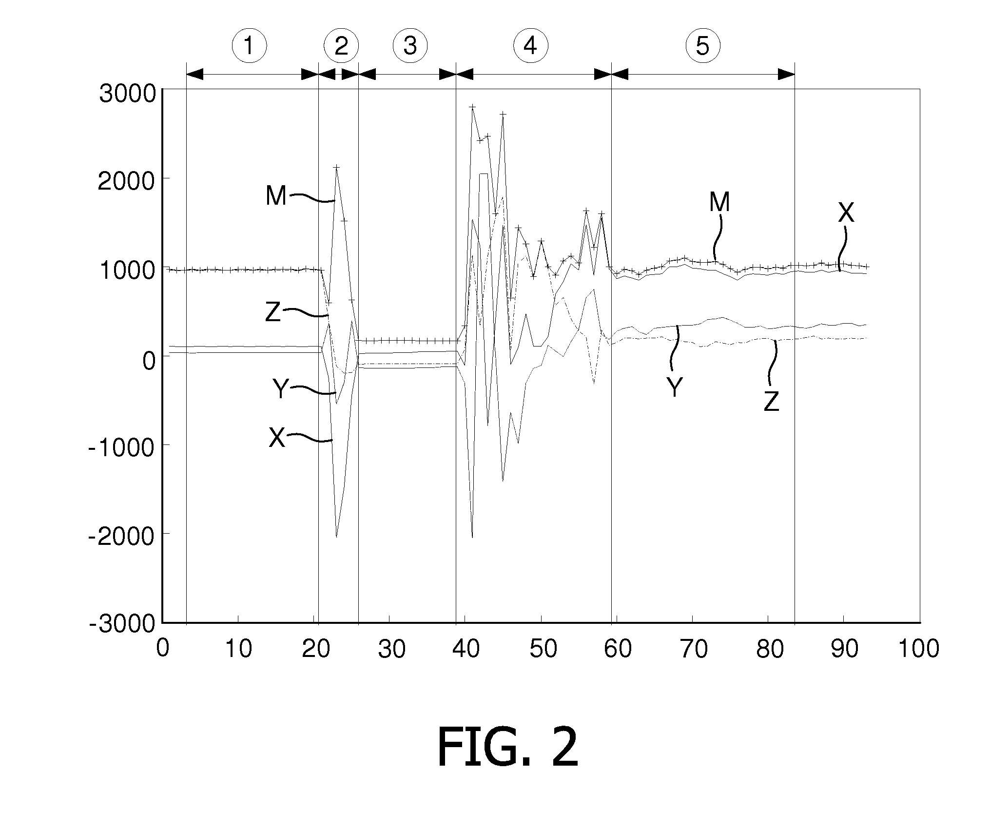
[0026]FIG. 2 represents the acceleration data X, Y, Z as measured during the fall of a sensor module 2, falling from a table onto the floor. FIG. 3 represents the acceleration data X, Y, Z as measured during the fall of a human, falling forward onto the floor. Both FIGS. 2 and 3 furthermore show the magnitude M that may for instance be calculated from:

M=√{square root over (X2+Y2+Z2)}  (1)

or from:

M=|X|+|Y|+|Z|  (2)

[0027]The acceleration data in FIG. 2 can be divided in five distinct phases, marked ① to ⑤:[0028]a first phase ①, during which the acceleration data X, Y, Z, M are substantially stable. This corresponds with the sensor module 2 lying still on the table;[0029]a second phase ②, during which the acceleration data X, Y, Z, M fluctuate in all three directions. This corresponds with the sensor module 2 being pushed over the edge of the table, so as to start its fall;[0030]a third phase ③, during which the acceleration data X, Y, Z remain substantial...

embodiment 2

Detection of One or More Full Rotations

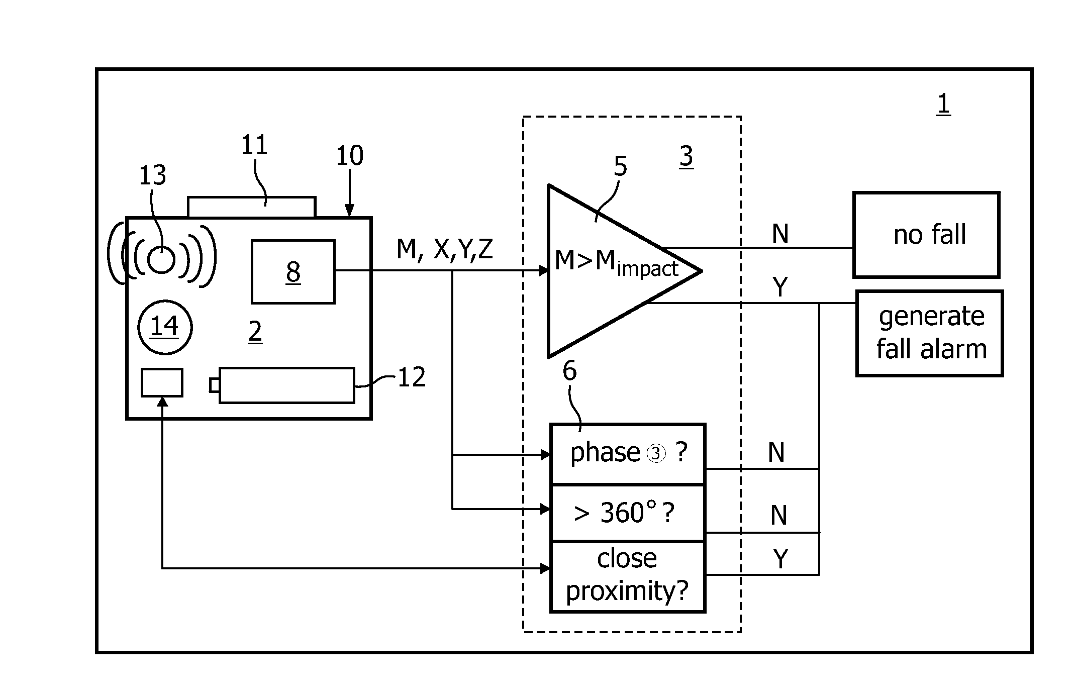
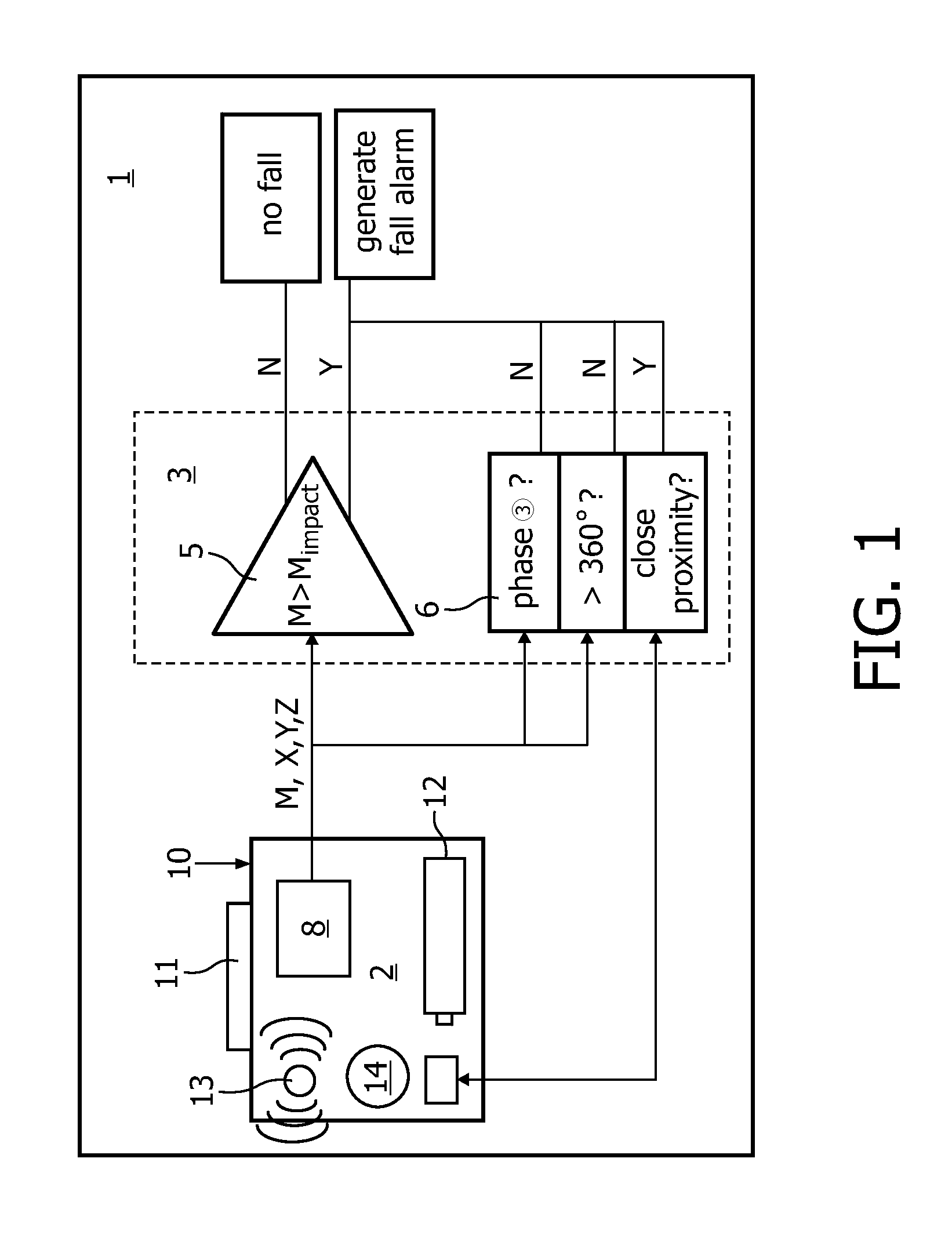
[0039]FIG. 5 schematically shows an embodiment of an alternative fall detection system 101 according to the invention, with alternative or additional second evaluation logic 106. Components that are similar to those of embodiment 1 have been identified with similar reference numerals, increased by 100. The second evaluation logic 106 makes use of the insight that small objects, such as a sensor modules 102, tend to make one or more full rotations (i.e. rotate over more than 360 degrees) when falling from a certain height. Persons, on the other hand, will usually not make such full rotations. This insight can therefore be used to distinguish between an accidental drop of the sensor module 102 and a human fall incident.

[0040]The detection system 101 according to FIG. 5 comprises a sensor module 102 and first evaluation logic 105 that may be similar to that described in FIG. 1. The sensor module 102 may be provided with one or more angular sensors...

embodiment 3

Detection of Close Proximity of Sensor Module and the User's Body

[0043]According to yet another embodiment of the invention, false alarms due to accidental falling of the sensor module may be prevented by having the second evaluation logic verify whether the sensor module is in close proximity of the human body (and thus likely to be worn) at the moment of an observed impact. To that end the second evaluation logic may for instance comprise a sensor, which may be accommodated in the sensor module and which is capable of sensing distortion of an electrical field caused by the user's body moving into or out of said field. A suitable sensor is for instance an electrical field sensor, as described in the article “Applying electrical field sensing to Human-Computer interfaces”, of authors T. G. Zimmerman, et al., published in IEEE, May 1995.

[0044]If, upon the detection of a potential fall incident (by for instance first evaluation logic as described in relation to the previous embodiment...


PUM


Abstract

The invention relates to a fall detection system, for detecting human fall incidents. The detection system comprises a sensor module to be worn by a user, for collecting motion data of his body, for instance acceleration data; first evaluation logic for identifying a potential fall incident on the basis of an impact observed in the acceleration data; and second evaluation logic for verifying that the sensor module is actually worn by the user, at least around the time of said impact, to prevent the system from raising an alarm if only the sensor module has fallen. The second evaluation logic may comprise free fall detection means for evaluating the acceleration data on characteristics which are typical for a free falling object, such as one or more full rotation and/or a free falling phase, during which the magnitude of the acceleration data is relatively stable and small. Additionally or alternatively the second evaluation logic may comprise body proximity detection means for detecting whether the sensor module is in close proximity to the human body.

Description

FIELD OF THE INVENTION[0001]The invention relates to a fall detection system, for automatically detecting fall incidents of a user.BACKGROUND OF THE INVENTION[0002]Such automatic fall detection systems are known. They are used to detect fall incidents of a user and report such incidents to a remote care provider who may then take appropriate action. To that end, the detection systems generally comprise a sensor module, to be worn by the user, for collecting movement data of his body, for instance acceleration data. The detection systems further comprise evaluation logic, to detect an impact in the collected movement data. Such impact will occur when the user hits the ground during a fall. However, such impacts may also occur through other events, such as a sudden movement of the user or a collision with his environment. Consequently, the detection of an impact in the acceleration data is not sufficient to positively identify the occurrence of a fall. Therefore, most detection system...

Claims


Application Information

Patent Timeline
Patent Type & Authority Applications(United States)
IPC IPC(8): A61B5/11
CPCA61B5/1117G08B21/0446A61B2562/0219
Inventor TEN KATE, WARNERFLINSENBERG, INGRID CHRISTINA MARIACHEN, NINGJIANGKIM, SHENGSCHLUMBOHM, STEPHANSCHONENBERG, RUDIE BERNARDUS MARIA
Owner KONINKLIJKE PHILIPS ELECTRONICS NV
Why Eureka
Try Eureka