
Liquid ejecting head and liquid ejecting apparatus

a liquid ejector and head technology, applied in printing and other directions, can solve the problems of reducing the size of the liquid ejector head, wiring, etc., and is more complex, and achieves the effect of reducing the risk of poor mounting and reducing the head siz

Active Publication Date: 2010-05-20
SEIKO EPSON CORP
View PDF1 Cites 4 Cited by
  • Summary
  • Abstract
  • Description
  • Claims
  • Application Information

AI Technical Summary

Benefits of technology

[0007]An advantage of some aspects of the invention is to provide a liquid ejecting head that features a reduced size without sacrificing reliability and to provide a liquid ejecting apparatus that includes such a liquid ejecting head.

Problems solved by technology

A structure in which a fixation plate is provided for each nozzle line for fixation to a head case has many disadvantages in reducing the size of a liquid ejecting head.
In addition, wiring, etc., is more complex.

Method used


Image

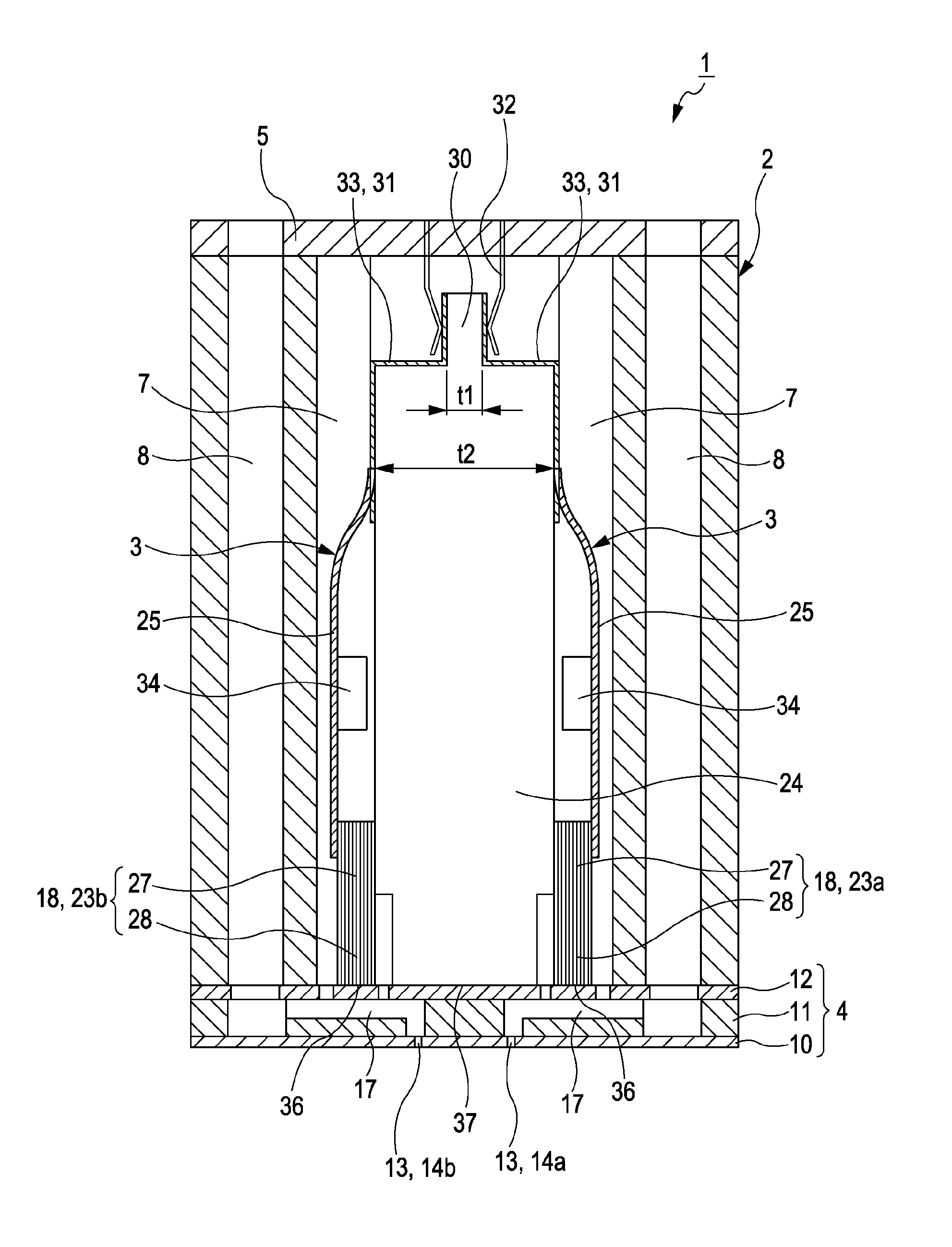
  • Liquid ejecting head and liquid ejecting apparatus
  • Liquid ejecting head and liquid ejecting apparatus
  • Liquid ejecting head and liquid ejecting apparatus

Examples


Embodiment Construction

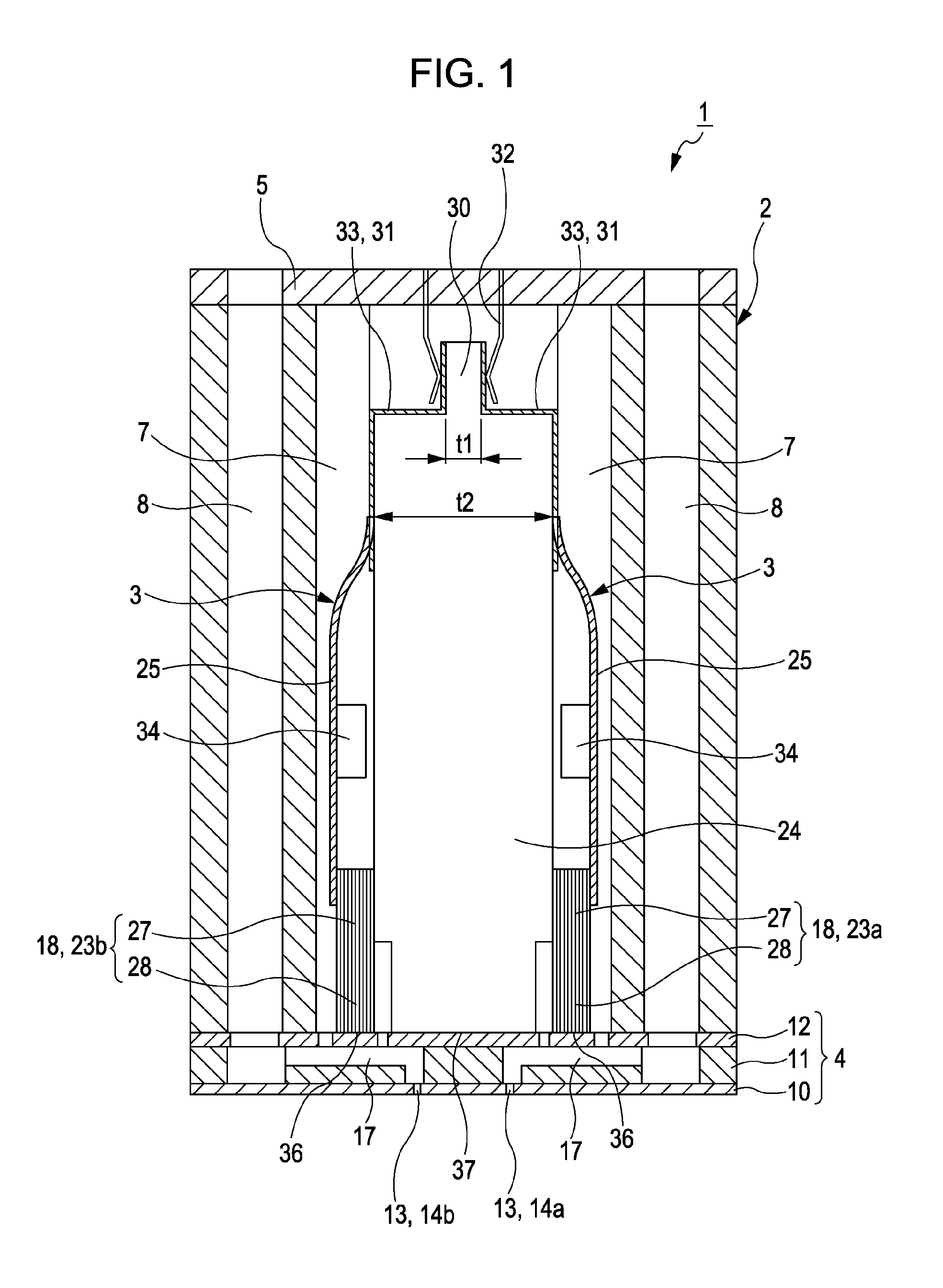
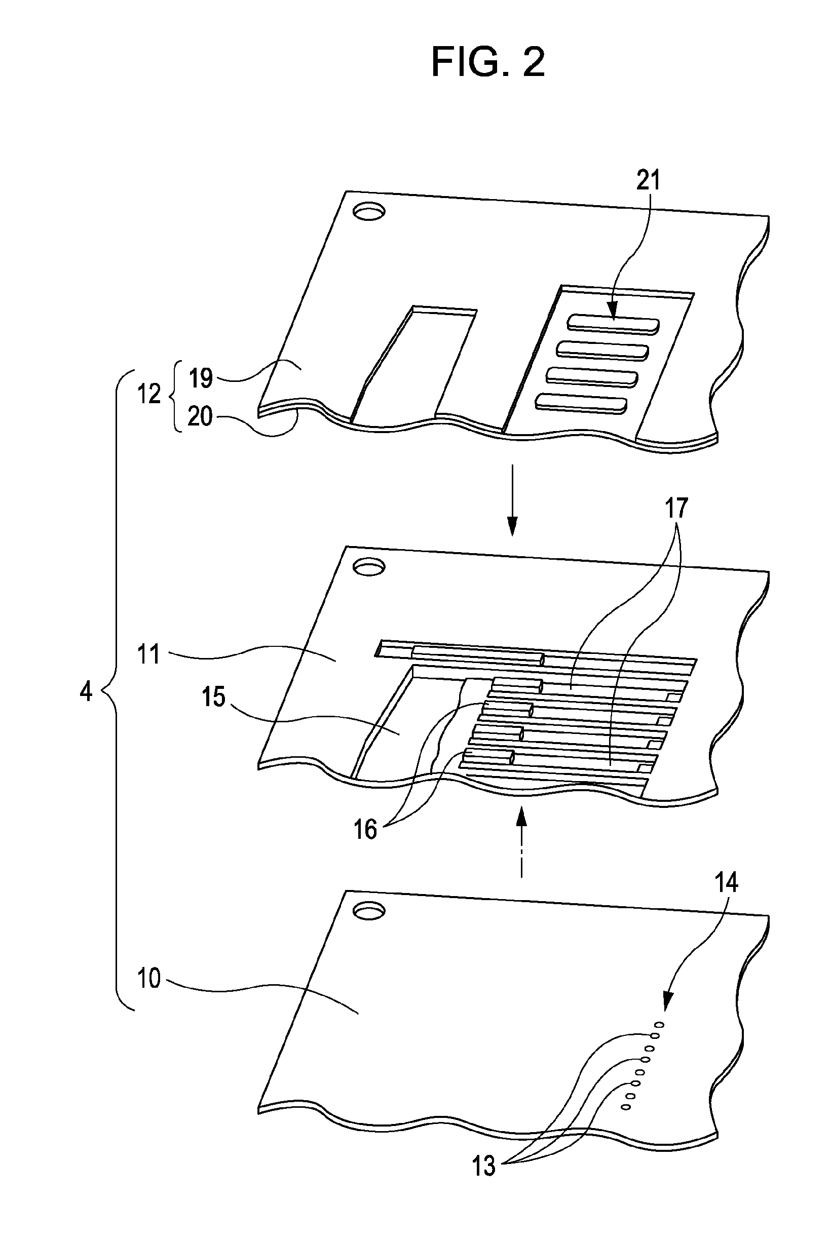
[0031]With reference to the accompanying drawings, the best mode for carrying out the present invention will now be explained in detail. Although various specific features are explained in the following exemplary embodiments of the invention for the purpose of disclosing preferred modes thereof, the scope of the invention is not limited to the specific embodiments described below unless any intention of restriction is explicitly shown. The invention may be modified, altered, changed, adapted, and / or improved without departing from the gist and / or spirit thereof apprehended by a person skilled in the art from explicit and implicit description given herein. In the following description, an ink-jet recording apparatus is taken as an example of a liquid ejecting apparatus according to an aspect of the invention. The ink-jet recording apparatus may be hereinafter simply referred to as a “printer”. In addition, an ink-jet recording head is taken as an example of a liquid ejecting head acc...


PUM


Abstract

A liquid ejecting head includes pressure generation elements that apply pressure change to liquid retained in corresponding pressure generation chambers to discharge the liquid from corresponding nozzle openings. Each of the pressure generation elements is fixed to a fixation plate. Nozzle lines include nozzle openings arrayed in a line. An electrical signal is sent through a flexible substrate from the outside to the pressure generation chambers. Pressure generation elements associated with the pressure generation chambers are fixed to the fixation plate, with the fixation plate being positioned between the pressure generation elements of each of two parallel nozzle lines. A wiring portion is formed at one end part of the fixation plate opposite to the other end that is closer to the pressure generation chambers. The flexible substrate is connected to the wiring portion.

Description

BACKGROUND[0001]1. Technical Field[0002]The present invention relates to a liquid ejecting head such as an ink-jet recording head that ejects, utilizing a pressure change, liquid drops from nozzle openings. In addition, the invention relates to a liquid ejecting apparatus that is provided with such a liquid ejecting head.[0003]2. Related Art[0004]A liquid ejecting apparatus is provided with a liquid ejecting head that can eject liquid. Having such a liquid ejecting head, a liquid ejecting apparatus is capable of ejecting various kinds of liquid. An example of a liquid ejecting apparatus is an image recording apparatus such as an ink-jet printer. An ink-jet printer is provided with an ink-jet recording head, which is an example of various kinds of a liquid ejecting head. An ink-jet printer performs recording by ejecting ink in the form of ink drops from nozzles of the ink-jet recording head toward a recording target medium such as a sheet of printing paper or the like. As a result of...

Claims


Application Information

Patent Timeline
Patent Type & Authority Applications(United States)
IPC IPC(8): B41J2/04
CPCB41J2/14274
Inventor OKAZAWA, NORIAKI
Owner SEIKO EPSON CORP
Learn More