Switching Circuit Layout With Heatsink

a heatsink and circuit technology, applied in the direction of cross-talk/noise/interference reduction, electrical apparatus contruction details, printed circuit non-printed electric components association, etc., can solve the problems of static and dynamic power loss in any switching inverter/converter, increase in frequency can have the undesirable effect of increasing electromagnetic interference (emi),

Active Publication Date: 2010-05-20
SOLAREDGE TECH LTD
View PDF99 Cites 149 Cited by
  • Summary
  • Abstract
  • Description
  • Claims
  • Application Information

AI Technical Summary

Benefits of technology

[0013]According to yet another embodiment of the present invention there is provided a switching converter having multiple switches including a first switch, a second switch, a third switch and a fourth switch. A circuit board has a layout for connecting the switches. The layout locates the switches substantially at the endpoints of a right-angle cross or substantially symmetrically with respect to the endpoints of the right-angle cross. The switches are interconnected in a full bridge switching topology. The switches are interconnected in a buck-boost switching topology. A heat-sink is operatively attached to the switches for conducting heat from the switches. The switches are preferably insulated gate bipolar junction transistors (IGBT). The layout includes cutouts for the switches, having a chassis mounting for the insulated gate bipolar junction transistors; and a heat sink attached to the transistors and the chassis. The right-angle cross is formed from two line segments intersecting with a ninety degree angle. The circuit board may offset the switches perpendicularly to the line segments at the endpoints of the line segments either in a clockwise or a counterclockwise direction, thereby forming the layout of the switches in the shape of a fylfot cross. The first switch and the third switch are at the endpoints of the first line segment forming a first pair of the switches and the second switch and the fourth switch are at the endpoints of the second line segment forming a second pair of the switches. The switching converter switches alternately the first pair of switches and the second pair of switches. The right-angle cross is formed from two line segments intersecting with substantially a ninety degree angle. The circuit board may offset only two of the switches perpendicularly to one of the line segments at the endpoints of the one line segment either in a clockwise or an counterclockwise direction. The switching converter is mounted vertically so that the one line segment is substantially vertical and one of the two switches is substantially below the second of the two switches so that while the switching converter is operating, the heat from the lower of the two switches does not flow near the upper of the two switches. The first switch, the second switch, the third switch and the fourth switch may include: silicon controlled rectifier (SCR), insulated gate bipolar junction transistor (IGBT), bipolar junction transistor (BJT), field effect transistor (FET), junction field effect transistor (JFET), switching diode, electrical relay, reed relay, solid state relay, insulated gate field effect transistor (IGFET), diode for alternating current (DIAC), and / or triode for alternating current TRIAC.

Problems solved by technology

However, the increase in frequency can have the undesirable effect of increasing electromagnetic interference (EMI) if good circuit design and good circuit layout practices are not followed.
Both static and dynamic power losses occur in any switching inverter / converter.

Method used


Image

  • Switching Circuit Layout With Heatsink
  • Switching Circuit Layout With Heatsink
  • Switching Circuit Layout With Heatsink

Examples


Embodiment Construction

[0027]Reference will now be made in detail to embodiments of the present invention, examples of which are illustrated in the accompanying drawings, wherein like reference numerals refer to the like elements throughout. The embodiments are described below to explain the present invention by referring to the figures.

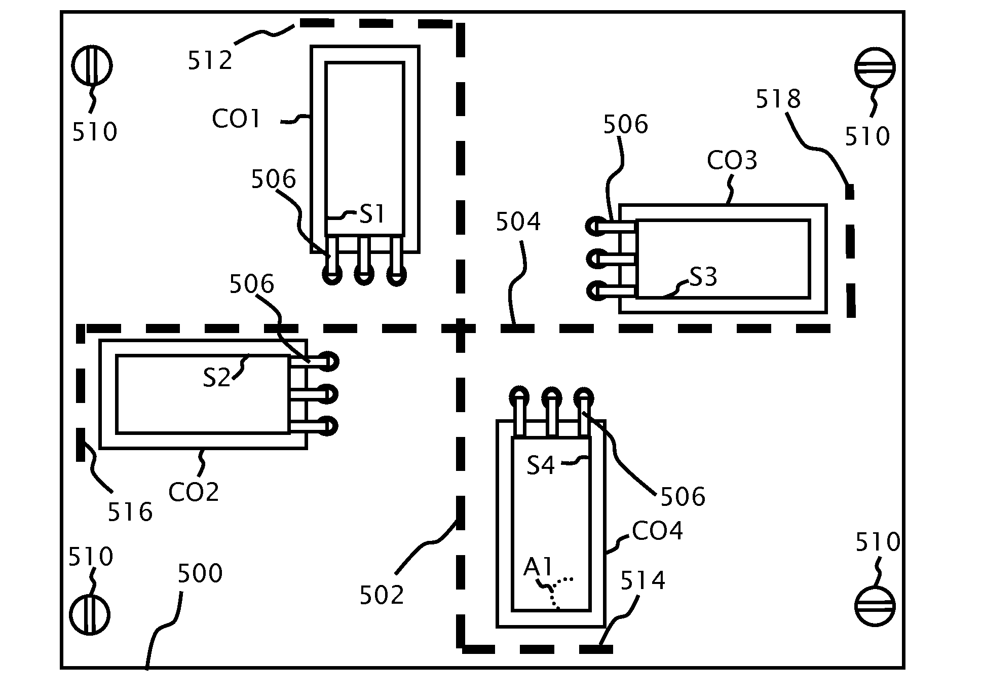
[0028]By way of introduction, an intention of embodiments of the present invention is to minimize the lengths of the conductors between switches of a switching converter / inverter, minimizing interference due to parasitic capacitance and inductance, reducing electro-magnetic interference (EMI) emissions and thereby maximizing the efficiency of the switching converter.

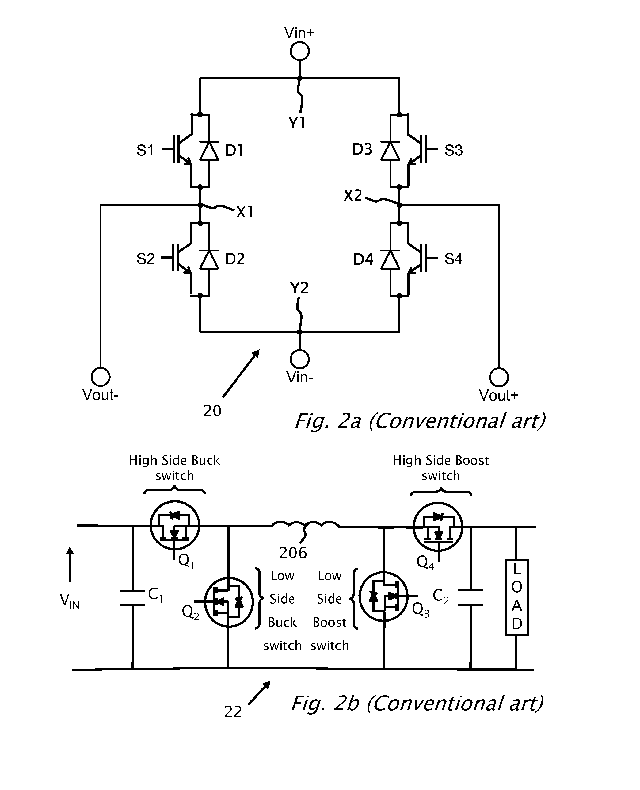
[0029]It should be noted, that although the discussion herein relates to switching topology for a four insulated gate bipolar junction transistors (IGBT) full bridge inverter, the present invention may, by non-limiting example, alternatively be configured as well using other types of DC-DC converters AC-DC inve...


PUM


Abstract

A circuit board adapted for use in an switching converter for connecting a plurality of switches including a first switch, a second switch, a third switch and a fourth switch. The circuit board has a layout for connecting the switches. The layout is adapted for locating the switches substantially at or symmetrically with respect to the endpoints of a right-angle cross. The right-angle cross is formed from two line segments intersecting with a ninety degree angle. The circuit board may offsets the switches perpendicularly to the line segments at the endpoints of the line segments either in a clockwise or a counterclockwise direction.

Description

CROSS REFERENCE TO RELATED APPLICATIONS[0001]The present application benefits from U.S. provisional application 61 / 060,878 filed on Jun. 12, 2008 by the present inventors.BACKGROUND[0002]1. Technical Field[0003]The present invention relates to switching converters and to specifically a circuit layout of four switches[0004]2. Description of Related Art[0005]The thermal resistance of materials used to package electronic components is of great interest to electronic engineers, because most electrical components generate heat and need to be cooled. Electronic components need to be cooled to avoid premature aging and consequent failure. Also, effective cooling of the electronic component(s) susceptible to generating heat in a circuit allows for a stable, efficient and predictable performance of the circuit. In particular, heat generated from electronic components in power supply / conversion circuits are mostly derived from the main switching devices.[0006]Heat sinks function by efficientl...

Claims


Application Information

Patent Timeline
Patent Type & Authority Applications(United States)
IPC IPC(8): H05K7/20
CPCH02M7/003H05K1/0203H05K1/021H05K1/0216H05K2201/10522H05K1/182H05K3/0061H05K2201/09418H05K2201/10166H05K1/18
Inventor HANDELSMAN, LIORGLOVINSKY, TZACHIGROSSBERG, AMIRROGALIA, SONKESCHMIDT, HERIBERT
Owner SOLAREDGE TECH LTD
Why Eureka
Try Eureka