Surgical device, system and method of use thereof

a surgical device and a technology of a surgical device, applied in the field of surgical devices, systems and methods, can solve the problems of fractures, less than optimal mechanism of such staples, and a large amount of percussive force applied to drive the staples, and achieve the effect of repairing a bone fractur

Active Publication Date: 2010-05-20
MBRACE
View PDF22 Cites 27 Cited by
  • Summary
  • Abstract
  • Description
  • Claims
  • Application Information

AI Technical Summary

Benefits of technology

[0017]The guide device can include an adjustable assembly, wherein said adjustable assembly further comprises at least one aperture capable of accepting a drill, and wherein said apertures further comprise detachably attachable inserts capable of accepting at least one guide wire. The user can place the guide device in a desired position over a bone fracture, adjust the positions of the apertures having inserts attached to guide insertion of said guide wires into bone. The user can then insert guide wires through these inserts of the apertures and into bone fragments and remove the inserts while leaving the guide device in place. The user can then use the guide device to accept a drill therethrough, wherein the drill has a drill bit with a hole running axially through it, and can thus place the drill bit over the guide wires to bore holes around the guide wires and into the bone fragments. After the holes are drilled, the drill and guide device can be removed so that the staple can be inserted over the guide wires and into the bone. Afterwards, the user can remove the guide wires, thereby inserting the staple into the bone fragments and repairing a bone fracture.
[0019]A method for using a surgical staple is also disclosed. According to the method, the practitioner places two guide wires in bone, in a desired position on each side of a bone fracture. Holes are bored into the bone fragments over the two guide wires, a grooved and tabbed surgical staple is aligned with the guide wires and inserted into the holes in the bone. The guide wires are removed and the staple is compressed so that the staple stabilizes the bone fragments to repair a bone fracture. The insertion of the guide wires can be aided by placing a guide device over the bone fracture. The holes in the bone can be bored with a cannulated drill placed over the guide wires and the guide wires' positions can be confirmed fluoroscopically. Further, a depth gauge can be used to measure the exposed length of the inserted guide wires to determine the length of the staple's legs to be used. A device such as a mallet or tamp can be used to seat the inserted grooved and tabbed surgical staple and the staple's position can be confirmed fluoroscopically.
[0021]In yet another embodiment, the surgical device for compression or distraction of a first body part relative to a second body part comprises a bridge having a first leg and a second leg extending from a same side of the bridge. The first leg can be inserted into a first body part and the second leg can be inserted into a second body part. The bridge further comprises at least one adjustable anti-reversing portion. The adjustable anti-reversing portion(s) can provide a known amount of compression or distraction of the first and second body parts when the staple is surgically implanted. This embodiment of the device can further comprise an aperture positioned between two adjustable anti-reversing portions in the bridge or at least one aperture in the adjustable anti-reversing portion that is capable of receiving an instrument, whereby a user can insert the instrument into the aperture and adjust the adjustable anti-reversing portions to provide compression or distraction. The adjustable anti-reversing portion of this embodiment can be comprised of a hinged system, a one-way sliding track system, a ratchet system, a gear and pawl system, a rack and pinion system, a one-way clutch system, or any other anti-reversing mechanism. Further, the first and second legs can be grooved or cannulated so that guide wires can guide the staple during its insertion.

Problems solved by technology

However, fractures may arise from driving the compound-shaped legs into the bone.
Also, the mechanism employed for such staples is less than optimal in that the staple's legs converge at their ends to create compression, which provides little to no compression at the bridge end of the staple.
A disadvantage of all of the aforementioned staples is that the percussive force applied to drive the staples is quite abrasive and a more controllable method of insertion would be a more advantageous surgical technique.
Also, there is no guidance prior to insertion for the precise placement of the staples.
Such staples and methods, however, have common insertion techniques that are extremely difficult to complete.
In many cases the holes are lost due to blood, debris, and soft issue in the surrounding area that fill into the holes.
Thus, it is difficult to accurately assess the location of the holes under fluoroscopy using this technique.
For these reasons, staples are placed inaccurately and the holes must be re-drilled to properly insert the staple and repair the bone.
However, such attempts are problematic for other reasons.
The prior art fails to teach an easy method of insertion that provides for precise placement of both legs of the staple at the same time.
Further, predrilled holes are not used for placement of the staple and the staple must be driven into the bone with percussive force.
Another disadvantage of cannulated staples is that they have hollow anchoring members and thus provide a weak structure for purposes of holding bone fragments together.
The current devices do not disclose a robust staple or an insertion technique that is precise, quick, not destructive to the bone, and easy.
Nor does the prior art disclose staples that can be easily used for distraction, e.g., maintaining an osteotomy open for re-alignment of bones.
The prior art also does not disclose a device that is capable of maintaining compression at a known amount for a set amount of time.
Further, the staples known in the prior art do not include detached legs that can be assembled with the bridge of the staple.

Method used


Image

  • Surgical device, system and method of use thereof
  • Surgical device, system and method of use thereof
  • Surgical device, system and method of use thereof

Examples


Embodiment Construction

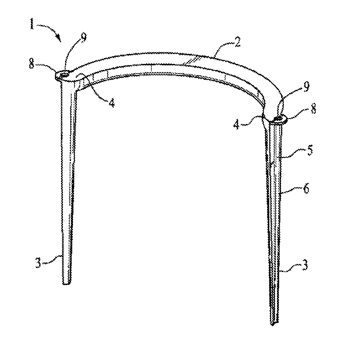
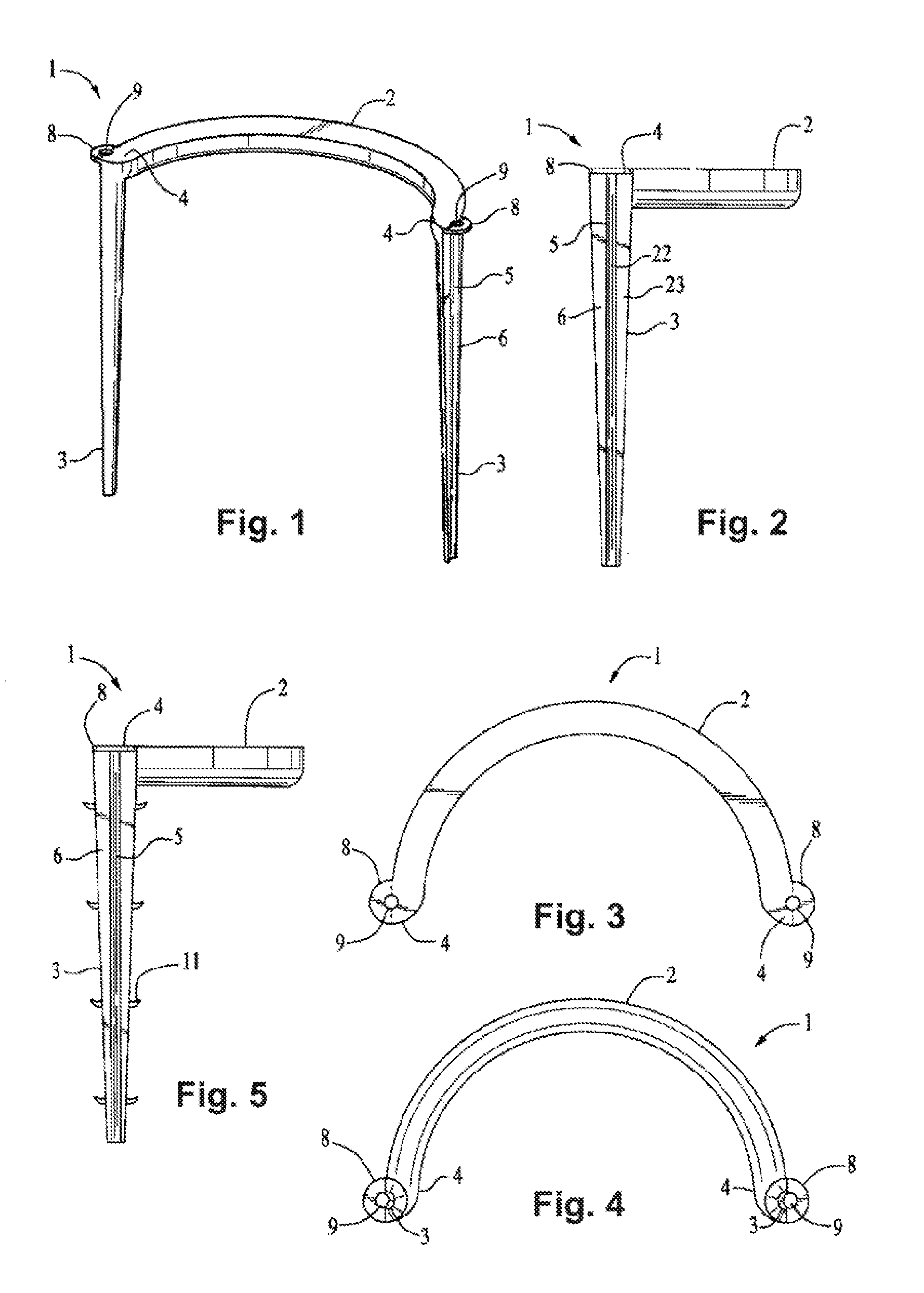
[0072]The present invention overcomes disadvantages of the prior art, as identified and disclosed by the inventor, by providing an improved compression staple and an easy-to-use system and method for its insertion for the internal fixation of bone fractures, fusions, and osteotomies. More specifically, the present invention includes a robust grooved and tabbed surgically implantable staple and can be easily inserted over guide wires and across a fractured bone to provide stability and compression across the desired site. The compression staple can be made of a shape memory metal material or alloy, such as nickel titanium, or another metal material or alloy, such as stainless steel or titanium. The staple is preferably made of a non-corrodable metal material compatible with use in the body. The staple may also be made of a bio-absorbable material. Other materials used for bone fixation include vitalium, chrome cobalt, and suitable bio-compatible polymeric materials.

[0073]Different em...


PUM


Abstract

The present invention includes a surgically implantable device, system, and method of use thereof for the internal compression or distraction of, for example, bone fractures, fusions, and osteotomies. More specifically, the surgical device comprises a bridge with one or more adjustable anti-reversing portions. The adjustable anti-reversing portion(s) may be located in a symmetrical or asymmetrical manner on the bridge between the device's legs. The adjustable anti-reversing portion(s) allow for stronger compression of the bone at a known amount of compression. The adjustable anti-reversing portion(s) can also maintain the device's legs in closer proximity to one another for greater compression or maintain the device's legs apart from one another for distraction. The surgical device can also comprise cannulated or grooved legs. A system and method of use is also described.

Description

CROSS-REFERENCE TO RELATED APPLICATIONS[0001]This application is a continuation-in-part application of and claims priority to U.S. application Ser. No. 12 / 275,133, filed on Nov. 20, 2008, which is hereby incorporated by reference in its entirety.FIELD OF THE INVENTION[0002]The present invention relates to a surgical device, system, and method of use thereof. More specifically, the invention relates to a surgical device with at least one adjustable anti-reversing bridge portion, related tools, and a method for its easy insertion into bone or tissue during orthopedic surgical procedures.BACKGROUND OF THE INVENTION[0003]Surgical devices used to stabilize bones during orthopedic surgical procedures, such as compression staples, are well known in the art. To correct and heal bone fractures properly, staples are often used to keep bone fragments in position by holding and compressing the bone fragments together without motion. Various staples have been produced to provide compression in v...

Claims


Application Information

Patent Timeline
Patent Type & Authority Applications(United States)
IPC IPC(8): A61B17/84A61B17/00
CPCA61B17/0642A61B17/1728A61B17/1739A61B17/8004A61B17/8009A61B17/8023A61B2017/1775A61B2017/00407A61B2017/00867A61B2017/22038A61B17/8095A61B17/1757A61B17/8061A61B17/1775
Inventor KINMON, KYLEHELME, DANIEL
Owner MBRACE
Why Eureka
Try Eureka