Eureka AIR delivers breakthrough ideas for toughest innovation challenges, trusted by R&D personnel around the world.

High Velocity Low Impact Liquid Feed Distributor

Inactive Publication Date: 2010-05-27
UOP LLC
View PDF9 Cites 1 Cited by
  • Summary
  • Abstract
  • Description
  • Claims
  • Application Information

AI Technical Summary

Benefits of technology

[0006]The present invention solves one or more of the problems with prior art liquid distributors by providing a device that allows liquids to be introduced into a vessel at high velocities. The devices of this invention include features that quickly distribute the introduced high velocity liquid throughout a vessel while simultaneously reducing the velocity of introduced liquid.

Problems solved by technology

Introducing a liquid feed uniformly into a liquid filled vessel such as a contactor can be difficult.
Low liquid velocities in the distribution arms can lead to distributor fouling in certain applications.
For example, where solids are suspended in or formed in the liquid feed, the solids can foul the distribution arms and / or small holes because the liquid feed velocity is not great enough to prevent the solid materials from blocking or plugging the arms and holes.
This in turn can result in non-uniform liquid distribution.

Method used


Image

  • High Velocity Low Impact Liquid Feed Distributor
  • High Velocity Low Impact Liquid Feed Distributor
  • High Velocity Low Impact Liquid Feed Distributor

Examples


Embodiment Construction

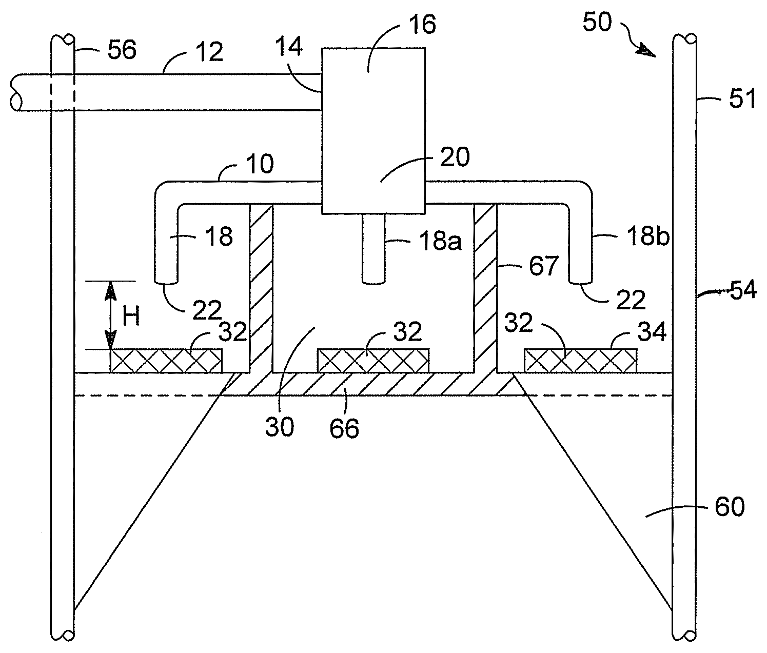
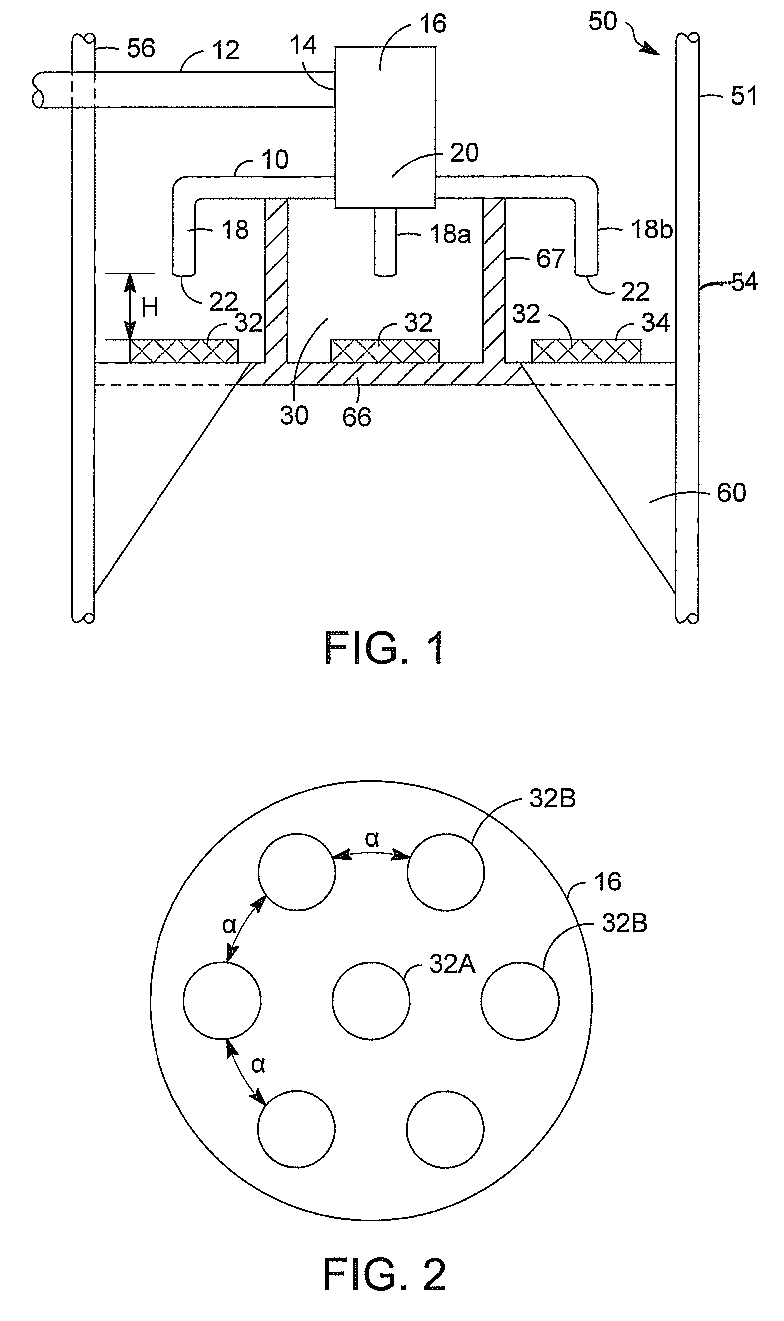
[0014]The present invention is directed to liquid distribution devices that are useful for quickly directing liquids moving at high initial velocities into liquid containing vessels and thereafter quickly reducing the velocity of the introduced liquid to uniformly distribute the introduced liquid in the vessel. Unlike liquid distributors of the prior art, the liquid distribution devices of this invention do not include small orifices. Therefore, the present invention solves at least some of the problems associated with distributing liquids at low velocity through a multitude of small orifices. The liquid distribution devices of this invention solve some of the prior art distribution problems because they include a plurality of liquid distribution pipes that direct liquids at high velocities towards opposing pans. When the high velocity liquid exiting the distribution pipe outlets impacts the pans, the liquid flow is redirected and further distributed causing a substantial reduction ...


PUM

PropertyMeasurementUnit
Heightaaaaaaaaaa
Heightaaaaaaaaaa
Distanceaaaaaaaaaa

Abstract

A liquid distribution device including a liquid distributor having an inlet pipe connected to a piping manifold that further includes a plurality of liquid distribution pipes each liquid distribution pipe including an inlet connected to the piping manifold and an outlet, and a liquid impact portion having a plurality of pans located in close proximity to the outlet of one or more of the liquid distribution pipes.

Description

BACKGROUND OF THE INVENTION[0001](1) Field of the Invention[0002]This invention concerns liquid feed distributors that are capable of distributing a high velocity feed with a corresponding low pressure drop with little to no fouling.[0003](2) Description of the Prior Art[0004]Introducing a liquid feed uniformly into a liquid filled vessel such as a contactor can be difficult. Often, distributors with complex distribution piping are used to uniformly distribute a liquid feed across a cross section of a vessel. Currently available distributors generally include primary and secondary distribution arms or manifolds. One or both of the primary and secondary distribution arms will typically include a multitude of small holes through which a liquid feed flows into a vessel. As a result of the number of distribution arms and the multitude of small holes, the pressure drop across the distributor—as the liquid feed flows through the distributor into the vessel—is very low. This correlates to ...

Claims


Application Information

Patent Timeline
IPC IPC(8): B65B3/04
CPCB01D3/008
Inventor VAN WEES, MARKSLAUGHTER, JOSEPH M.HEDRICK, BRIAN W.JOHNSON, BRIAN H.
Owner UOP LLC
Why Eureka
Eureka Blog
Learn More