Distributed clutter motion suppression through multiple moving transmit phase centers

Active Publication Date: 2019-07-25
SRC INC
View PDF22 Cites 7 Cited by
  • Summary
  • Abstract
  • Description
  • Claims
  • Application Information

AI Technical Summary

Benefits of technology

This patent relates to a system and method for reducing the velocity of the transmit phase center of a radar system relative to clutter, and to reduce the antenna beamwidth. The technical effect of this is that it improves the detection of ground moving targets, and, in particular, allows for the detection of slower moving targets or from a faster moving platform. By transmitting a plurality of transmit beams with an opposite motion to the carrier, the speed of the transmit phase center of each beam is reduced and effectively stationary with respect to clutter. This increases the likelihood of detection of slow-moving targets or from a faster-moving platform.

Problems solved by technology

Detecting ground moving targets is particularly difficult from a moving platform, such as an airplane, where the detection of slow targets in clutter is generally limited by the angular resolution available from the antenna beamwidth and the velocity of the platform.
Thus, it is difficult to detect very slow moving targets or to detect targets from a fast-moving platform such as an airplane.

Method used


Image

  • Distributed clutter motion suppression through multiple moving transmit phase centers
  • Distributed clutter motion suppression through multiple moving transmit phase centers
  • Distributed clutter motion suppression through multiple moving transmit phase centers

Examples


Embodiment Construction

[0023]Reference will now be made in detail to the present embodiments of the invention, examples of which are illustrated in the accompanying drawings. Wherever possible, the same reference numbers will be used throughout the drawings to refer to the same or like parts.

[0024]As a result of the various embodiments described herein, distributed clutter motion may be suppressed through multiple moving transmit phase centers.

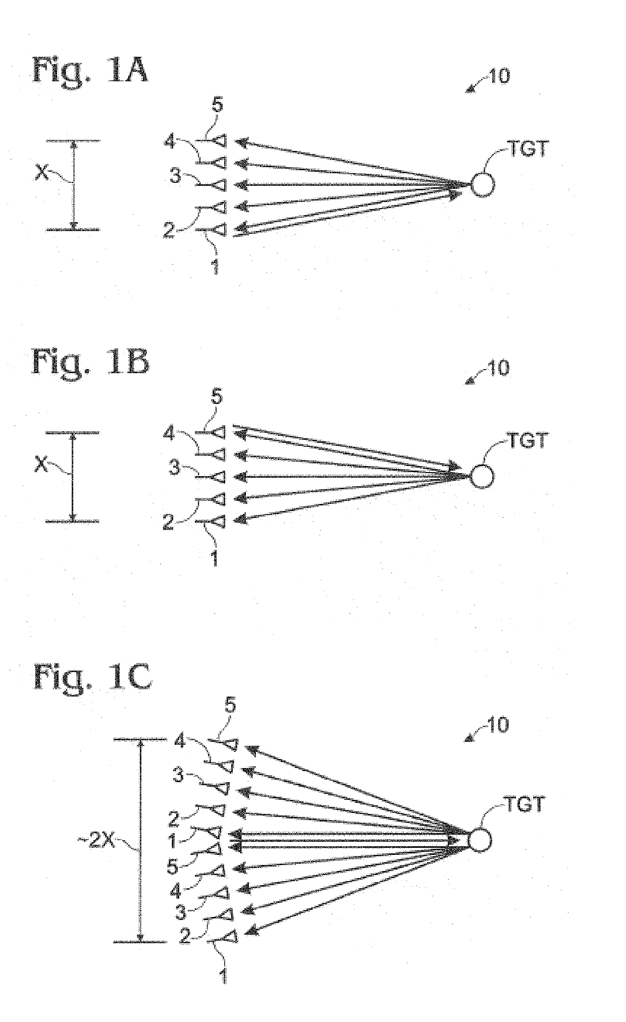
[0025]As embodied herein, and depicted in FIGS. 1A-1C, a diagrammatic depiction of a virtual array in accordance with the present invention is disclosed. FIGS. 1A-1C show a linear array of five antenna elements 1-5 and illustrates the benefit of using multiple transmit subarrays. In FIG. 1A, antenna element 1 is used as both a transmit phase center and a receive element. Antenna elements 2-5 are only used to receive. In FIG. 1B, antenna element 5 is used as both a transmit phase center and a receive element. Antenna elements 1-4 are only used to receive. If elements...


PUM


Abstract

A radar system located on an antenna array mounted on a moving carrier and including plurality of antenna elements; a transmitter portion coupled to the antenna and configured to transmit a plurality of transmit beams, each including a corresponding orthogonal transmit waveform of a plurality of orthogonal transmit waveforms, each of the plurality of transmit beams having a transmit phase center spatially located at a respective point along the antenna array, the transmitter portion being configured to transmit each transmit beam during at least a portion of a pulse repetition interval, wherein the transmitter portion is configured to shift the transmit phase center of each transmit beam for each pulse repetition interval to a respective point along the antenna array in a direction opposite the movement of the carrier, such that a speed of the respective transmit phase center of each beam remains is reduced.

Description

FIELD OF THE INVENTION[0001]The present invention relates generally to the field of RF communication systems, and particularly to radar systems.TECHNICAL BACKGROUND[0002]A radar is a system that uses electromagnetic waves to detect objects within a certain spatial volume. A radar system may be used to determine the range, altitude, direction, and / or speed of fixed objects, or objects that are moving through the spatial volume of interest. Radar systems have been used to identify and / or track various and disparate objects such as aircraft, ships, motor vehicles, weather formations, terrain, and baseballs. The term “radar” is an acronym for “RAdio Detection And Ranging.” As the name implies, a radar system transmits radio waves into the spatial volume referred to above. If and when a radio wave comes in contact with an object in space, the radio wave will be reflected and scattered by the object. Thus, a reflected signal is propagated back toward the radar system. The radar system rec...

Claims


Application Information

Patent Timeline
IPC IPC(8): G01S13/524G01S7/41G01S7/292G01S13/58G01S13/72
CPCG01S13/5244G01S7/414G01S7/415G01S7/292G01S13/582G01S13/723G01S13/90
Inventor CULKIN, DANIEL R.
Owner SRC INC
Why Eureka
Try Eureka