Bi-directional coupling with axial disengagement

Inactive Publication Date: 2010-05-27
SCHAEFFLER TECH AG & CO KG
View PDF9 Cites 2 Cited by
  • Summary
  • Abstract
  • Description
  • Claims
  • Application Information

AI Technical Summary

Problems solved by technology

Breese is limited in that the members are always rotationally fixed.
This combination requires a considerable amount of axial space in the transmission.
However, Kerr is limited in that once engaged, the co

Method used


Image

  • Bi-directional coupling with axial disengagement
  • Bi-directional coupling with axial disengagement
  • Bi-directional coupling with axial disengagement

Examples


Embodiment Construction

[0020]At the outset, it should be appreciated that like drawing numbers on different drawing views identify identical, or functionally similar, structural element of the invention. Furthermore, it is understood that this invention is not limited to the particular embodiments, methodology, materials and modifications described and as such may, of course, vary. It is also understood that the terminology used herein is for the purpose of describing particular aspects only, and is not intended to limit the scope of the present invention, which is limited only by the appended claims.

[0021]Unless defined otherwise, all technical and scientific terms used herein have the same meaning as commonly understood to one of ordinary skill in the art to which this invention belongs. Although any methods, devices or materials similar or equivalent to those described herein can be used in the practice or testing of the invention, the following methods, devices, and materials are now described.

[0022]F...


PUM


Abstract

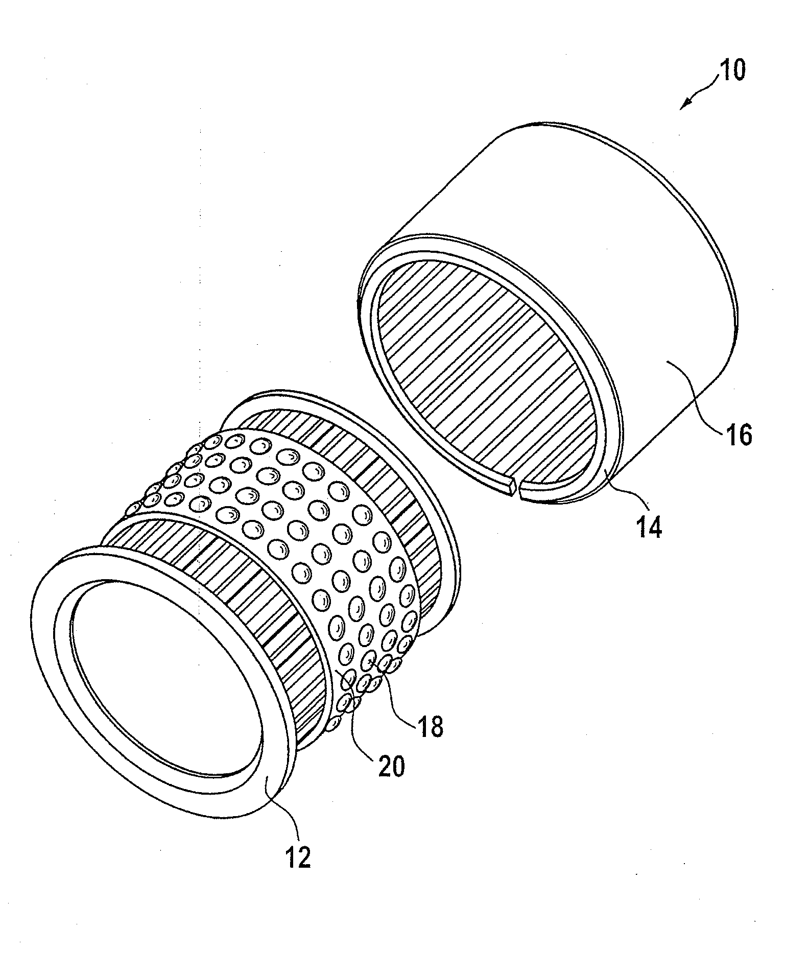
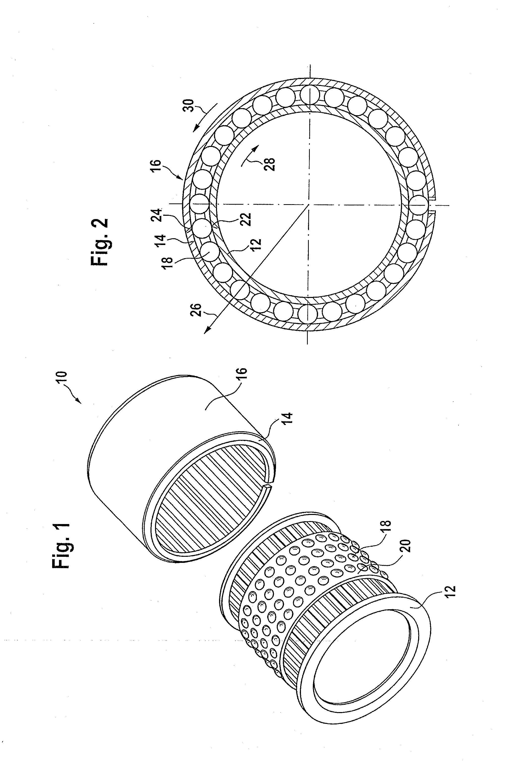
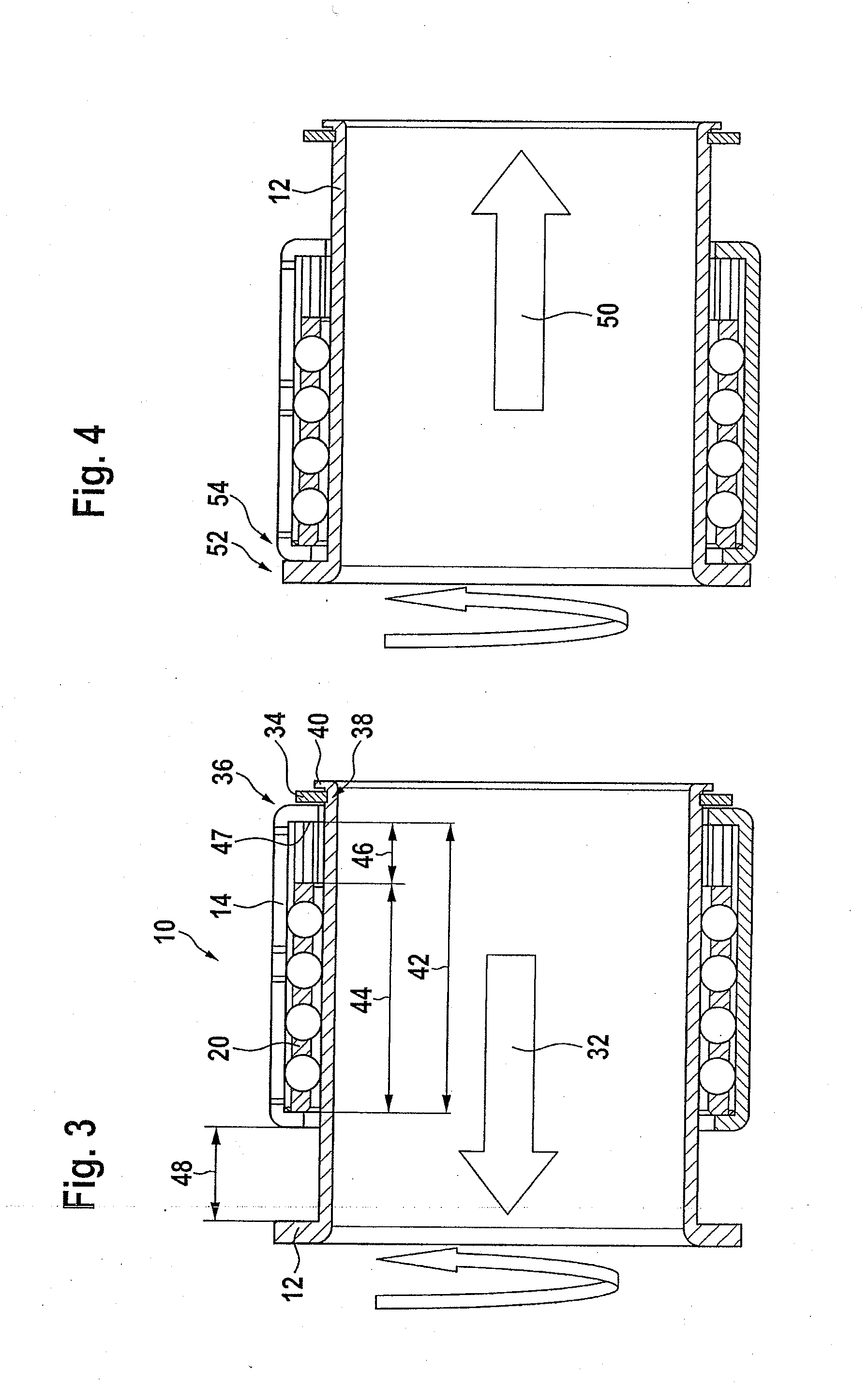
Example aspects of the present invention comprise two concentric rings, the rings movable relative to each other and defining a clearance between them for receiving at least one ball. The first ring is a coupling member, the second ring is a tubular slipper with a friction surface on the far side of the clearance, and the ball contacts the coupling member to the tubular slipper. At least one ring has a first recess with side walls for receiving the least one ball, and the friction surface is configured to displace in a radial direction when the at least one ball is axially aligned with the first recess and forced to run up the side walls by rotating the rings relative to one another. In an example embodiment of the invention, the first recess is a calotte.

Description

FIELD OF THE INVENTION[0001]The invention relates generally to a bi-directional coupling, and more specifically to a bi-directional clutch with axial disengagement.BACKGROUND OF THE INVENTION[0002]Couplings are commonly used to transmit torque from one rotating body to another body. Sometimes it is desirable to incorporate axial compliance in the coupling to allow the rotating bodies to move relative to one another. In this type of coupling, the two rotating bodies are rotationally fixed and axially movable. One application for this type of coupling is a driveshaft for a motor vehicle.[0003]U.S. Pat. No. 6,751,503 (Breese), hereby incorporated by reference in its entirety as if set forth fully herein, discloses a splined member for use in a slip joint for transmitting rotational force between two members, while accommodating a limited amount of relative axial movement therebetween. The slip joint includes a female splined member with a female tubular member and a plurality of elonga...

Claims


Application Information

Patent Timeline
IPC IPC(8): F16D41/064
CPCF16D41/105F16D15/00
Inventor LEE, BRIAN
Owner SCHAEFFLER TECH AG & CO KG
Why Eureka
Try Eureka