
Main shaft transmission used for gear measurement center

A technology of spindle drive and gear measurement, applied in the field of measurement, can solve problems such as high cost, complicated debugging, maintenance, and difficult manufacturing and processing, and achieve the effects of simple maintenance, elimination of radial force, and solving the problem of slippage

Active Publication Date: 2015-04-08
XIAN HIGH TECH AEH INDAL METROLOGY
View PDF7 Cites 0 Cited by
  • Summary
  • Abstract
  • Description
  • Claims
  • Application Information

AI Technical Summary

Problems solved by technology

[0004] The purpose of the present invention is to provide a spindle transmission device for a gear measurement center to solve the problems of high cost, difficult manufacturing and processing, and complicated debugging and maintenance in the prior art

Method used


Image

  • Main shaft transmission used for gear measurement center
  • Main shaft transmission used for gear measurement center

Examples


Embodiment Construction

[0023] The present invention is described in detail below in conjunction with accompanying drawing:

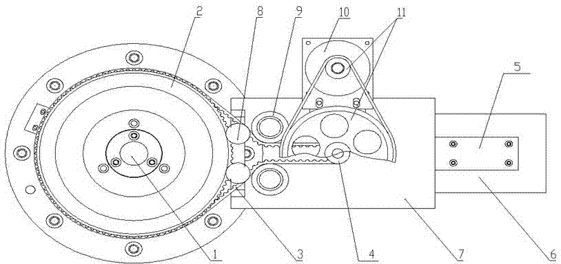
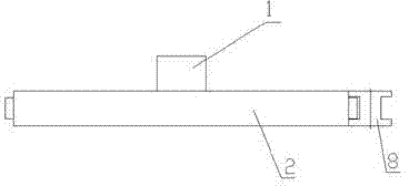
[0024] A spindle transmission device for a gear measurement center, comprising a measurement center spindle 1, a faceplate 2, a transmission belt 3, a transmission wheel 4 and a driving device, the transmission wheel 4 is connected to the drive device, the faceplate 2 is arranged on the measurement center spindle 1, and the faceplate 2 and the transmission wheel 4 transmit power through the transmission belt 3, and also include a base 6, a slide plate 7 and a pressing wheel 8, the base 6 is set on the radial side of the measurement center spindle 1, and the slide plate 7 is set on the base 6, the slide plate 7 and the base 6 are connected by the linear guide rail 5 arranged on the base 6, the linear guide rail 5 is arranged along the direction perpendicular to the measurement center spindle 1, and the driving device and the pressing wheel 8 are both arranged on the On the slid...


PUM


Abstract

The invention belongs to the technical field of measuring, and particularly relates to a man shaft transmission used for a gear measurement center. The problems that cost is high, manufacturing is difficult, and commissioning and maintenance are completed exist in the prior art. In order to solve the problems, the provided technical scheme is that the main shaft transmission used for the gear measurement center comprises a measurement center main shaft, a face plate, a transmission belt, a transmission wheel and a driving device, a base, a sliding plate and a pinch roller. The base is arranged on one side of the radial direction of the measurement center main shaft, the sliding plate is arranged on the base, the sliding plate is connected with the base through a linear guide rail arranged on the base, the driving device and the pinch roller are both arranged on the sliding plate, the pinch roller, the face plate and the transmission wheel are all arranged in a same plane, the pinch roller is arranged on the inner side of the transmission belt and between the face plate and the transmission wheel, and the pinch roller and the face plate are arranged in an external common tangent mode. Due to the fact that a common motor is adopted for transmission, the cost of a whole shafting is reduced.

Description

technical field [0001] The invention belongs to the technical field of measurement, and in particular relates to a main shaft transmission device for a gear measurement center. Background technique [0002] The gear measurement center can measure spur gears and helical spur gears of various shapes, measure gear hobs, worm gear hobs, shaving knives, radial shaving knives, gear shaping knives and other gear tools, and can also measure worm gears, Worm straight bevel gear, helical bevel gear, cam and other workpieces. It is widely used in scientific research departments and factory measurement rooms such as automobiles, machine tools, instruments, aviation, aerospace, and national defense industries. [0003] At present, because the gear measurement center has high requirements on the rotation accuracy of the measurement center spindle, the measurement center spindle will be biased by the tension generated by the belt when using ordinary motors and belt drives, thus affecting ...

Claims


Application Information

Patent Timeline
Patent Type & Authority Patents(China)
IPC IPC(8): G01M13/02F16H7/02F16H7/08F16H7/18
Inventor 徐少臣何建国柳涛朱阳光
Owner XIAN HIGH TECH AEH INDAL METROLOGY
Learn More