Winding-free end-part spiral-motion induction motor

A technology of induction motor and spiral motion, applied in the direction of electrical components, electromechanical devices, electric components, etc., can solve the problems of complex mechanical structure, high processing cost, large device volume, etc. Effect

Inactive Publication Date: 2014-02-26
HENAN POLYTECHNIC UNIV
View PDF2 Cites 0 Cited by
  • Summary
  • Abstract
  • Description
  • Claims
  • Application Information

AI Technical Summary

Problems solved by technology

The stator windings of the rotary motor and the linear motor of the device are arranged on a pot-shaped outer rotor. Since the outer rotor directly drives the output shaft, the moment of inertia is large and the bearing wear is serious
At the same time, the disclosed invention patent also has the disadvantages of complicated mechanical structure, high processing cost, large device volume and inconvenient use.

Method used


Image

  • Winding-free end-part spiral-motion induction motor
  • Winding-free end-part spiral-motion induction motor
  • Winding-free end-part spiral-motion induction motor

Examples


Embodiment Construction

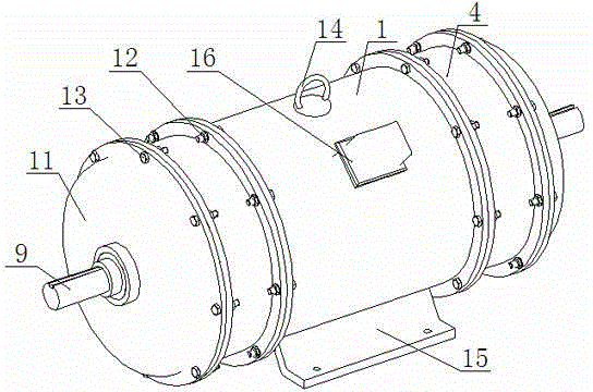
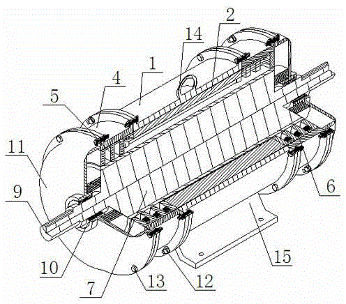
[0026] like Figures 1 to 14 As shown, the present invention includes a motor housing, a junction box 16 is arranged on the housing, a base 15 is arranged below the housing, and a stator core 2 at the straight part of the stator winding and a stator core 5 at the end of the stator winding are arranged in the housing. The stator core 2 of the straight part of the stator winding is formed by stacking silicon steel sheets with tooth grooves along the axial direction of the rotating shaft 9 , and the tooth grooves of the stator core 2 on the straight part of the stator winding form slots along the axial direction of the rotating shaft 9 . The stator core 5 at the end of the stator winding is provided at both ends of the stator core 2 in the straight part of the stator winding. The slots on the stator core 5 at the end of the stator winding form slots along the circumferential direction of the rotating shaft 9 and the axial direction of the rotating shaft 9 respectively. Slots are...


PUM


Abstract

The invention discloses a winding-free end-part spiral-motion induction motor which comprises a shell. The shell is internally provided with stator winding straight-line part stator iron cores and stator winding end part stator iron cores; the stator winding straight-line part stator iron cores and the stator winding end part stator iron cores are provided with stator windings; a rotating shaft is provided with a rotor of the motor; the surface of the rotor of the motor is provided with a conducting layer of the rotor; and the rotating shaft is movably connected with the shell through a sliding bearing. The winding-free end-part spiral-motion induction motor adopts a set of stator windings, the straight line parts of the stator windings can generate a rotating-motion magnetic field, two end parts of the stator windings can generate a linear-motion magnetic field, and the two magnetic fields jointly act on the rotor of the motor to directly drive a load to do spiral motion. The invention omits the end parts of the traditional motor, two end parts of the stator winding, which can generate linear motion magnetic field, are completely symmetric to stator iron cores on two ends of the motor in space, the radial force can be eliminated, and the wear of the bearing can be reduced. The invention is simple in structure, low in manufacturing cost and small in volume, is easy to implement and is convenient to use.

Description

technical field [0001] The invention relates to a motor, in particular to a spiral motion induction motor. Background technique [0002] In the production and processing industry, the drive motors of devices such as auger drilling machines, screw conveyors, screw compressors, plastic extruders, and screw pumps all need to drive the shaft to perform screw motion. The traditional technology realizes the helical motion of the drive shaft through the mechanical combination of multiple motors. The solution in the traditional technology is not only quite complicated in the control method, but also requires a lot of expensive, bulky and cumbersome mechanical transmission devices. In addition, since the transmission components and bearings bear large axial force, the mechanical wear of these components is quite large, and the equipment loss is serious. [0003] The invention patent with the publication number CN101107114 "Rotary Drive Device for Linear Medical Use for Injection Mol...

Claims


Application Information

Patent Timeline
Patent Type & Authority Patents(China)
IPC IPC(8): H02K41/025
Inventor 司纪凯许宝玉封海潮上官璇峰邵水军许孝卓司萌汪旭东
Owner HENAN POLYTECHNIC UNIV
Why Eureka
Try Eureka