Welding device

Active Publication Date: 2010-05-27
PANASONIC CORP
View PDF6 Cites 27 Cited by
  • Summary
  • Abstract
  • Description
  • Claims
  • Application Information

AI Technical Summary

Benefits of technology

[0009]The present invention aims to provide a welding device capable of achieving a quality welding as well as ca

Problems solved by technology

A wire supplying speed is thus not changed, but an output current or an appropriate welding voltage is changed, so that the welding cannot be done properly.
On top of that, a voltage corresponding to the prolonged section of the welding wire is not supplied, so that the welding v

Method used


Image

  • Welding device
  • Welding device
  • Welding device

Examples


exemplary embodiment 1

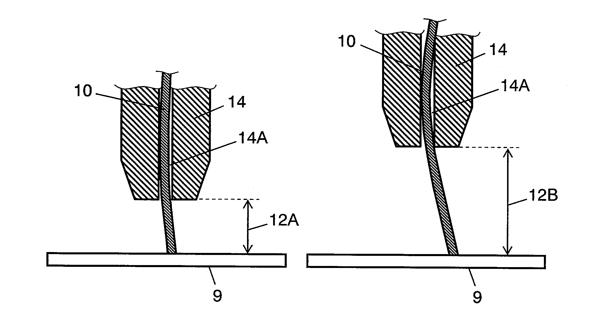
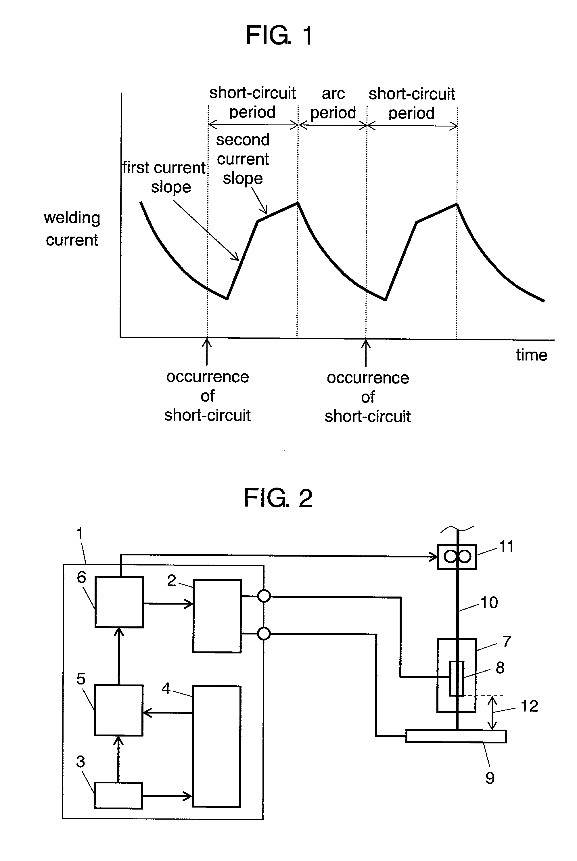
[0037]Before describing the welding device in accordance with the embodiment, the reason is explained with reference to FIG. 1 and Tables 1-4 why a welding condition in response to a feeder-work-piece distance of a welding tip must be used when the distance is different. FIG. 1 shows an instance of changes in welding current with time.

TABLE 1waveform controllingset valuewire supplyingrecommendedparameterof currentspeedvoltagefirst slope of current(A)(meter / minute)(V)(A / ms)15041680200619110250824160

[0038]Table 1 shows an instance of a set value of the welding condition in the following case: MAG welding of soft steel; wire diameter of 1.2 mm; and feeder-work-piece distance of 15 mm. When a welding current is set as table 1 shows, other parameters for waveform control are determined as shown in table 1. For instance, the welding current is set at 150 A, then a wire supplying speed is determined at 4 m / minute, a recommended welding voltage is determined at 16V, and a first current slop...


PUM

PropertyMeasurementUnit
Timeaaaaaaaaaa
Timeaaaaaaaaaa
Timeaaaaaaaaaa

Abstract

A welding device includes a welding torch, a memory, a power supply, an input section, a selector, and a controller. The welding torch includes a welding tip having a feeder for supplying electric power to a welding wire. The memory stores a plurality of welding conditions in which a feeder-work-piece to be welded distance is associated with at least one a length of the wire supplied per unit time, a weight of the wire supplied per unit time, and a set electric current. The power supply supplies electric power between the wire and the work-piece. The input section receives an input of a set value of a feeder-work-piece distance. The selector selects one of the welding conditions stored in the memory based on the set value. The controller controls the power supply based on the welding condition selected by the selector.

Description

TECHNICAL FIELD[0001]The present invention relates to a welding device which automatically supplies a consumable electrode (hereinafter referred to as a “wire”), and generates arc between the wire and an item to be welded (hereinafter referred to as a “work-piece”) to carry out a welding.BACKGROUND ART[0002]In recent years, the welding market has required increasing a speed of welding or reducing spatters. Welding at a higher speed will increase the number of work-pieces welded, while a reduction of spatters will decrease the number of steps in post treatments to remove spatters attached. Achievement of these requirements allows carrying out a quality welding steadily, which results in improving the welding productivity.[0003]A conventional welding device elaborately controls as many as several hundred types of waveform controlling parameters in order to improve the stability of high quality welding. The waveform controlling parameters have an optimum value for respective welding co...

Claims


Application Information

Patent Timeline
IPC IPC(8): B23K9/10B23K9/12
CPCB23K9/0953B23K9/09B23K9/173
Inventor KAWAMOTO, ATSUHIROMUKAI, YASUSHIFUJIWARA, JUNJIKOWA, MASARU
Owner PANASONIC CORP
Why Eureka
Try Eureka