Torsion beam axle having connecting tube between torsion beam and trailing arm

a technology of connecting tube and torsion beam, which is applied in the direction of pivoted suspension arms, endless track vehicles, transportation and packaging, etc., can solve the problems of easy damage to the coupling and the method of coupling the different materials between the trailing arm and the torsion beam is becoming an important problem, and expensive equipment is required

Inactive Publication Date: 2010-05-27
AUSTEM CO LTD
View PDF11 Cites 17 Cited by
  • Summary
  • Abstract
  • Description
  • Claims
  • Application Information

AI Technical Summary

Benefits of technology

[0012]According to the torsion beam axle of the present invention, the trailing arms and the torsion beam which make use of different materials are coupled via the connecting tubes that are integrally coupled with the trailing arms, so that the coupling force between the trailing arms and the torsion beam can be improved. Particularly, the connecting tubes are welded with the torsion beam by using a material that is better than that of the trailing arms with respect to weldability with the torsion beam, so that the coupling force between the trailing arms and the torsion beam can be improved,

Problems solved by technology

The torsion beam axle has major technical problems in that it must enable good performance of an independent suspension system by implementing a torsion beam having a concurrent torsion characteristic when torsion occurs between the left-hand wheel and the right-hand wheel and simultaneously secure trunk space and price competitiveness, and in that it must make the chassis light by means of an optimized design of the torsion beam.
In this respect, the method of coupling the different materials between the trailing arms and the torsion beam is becoming an important problem.
However, due to weak coupling strength, the coupling between the trailing arms and the torsion beam has been easy to damage.
To this end, expensive equipment has been required, which weakens competitiveness from the aspect of production cost.

Method used


Image

  • Torsion beam axle having connecting tube between torsion beam and trailing arm
  • Torsion beam axle having connecting tube between torsion beam and trailing arm
  • Torsion beam axle having connecting tube between torsion beam and trailing arm

Examples


Embodiment Construction

[0022]Reference will now be made in greater detail to a preferred embodiment of the invention, an example of which is illustrated in the accompanying drawings. Wherever possible, the same reference numerals will be used throughout the drawings and the description to refer to the same or like parts.

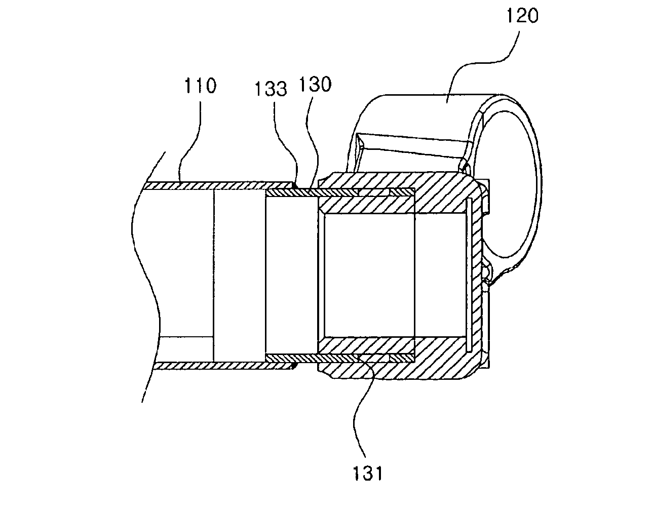
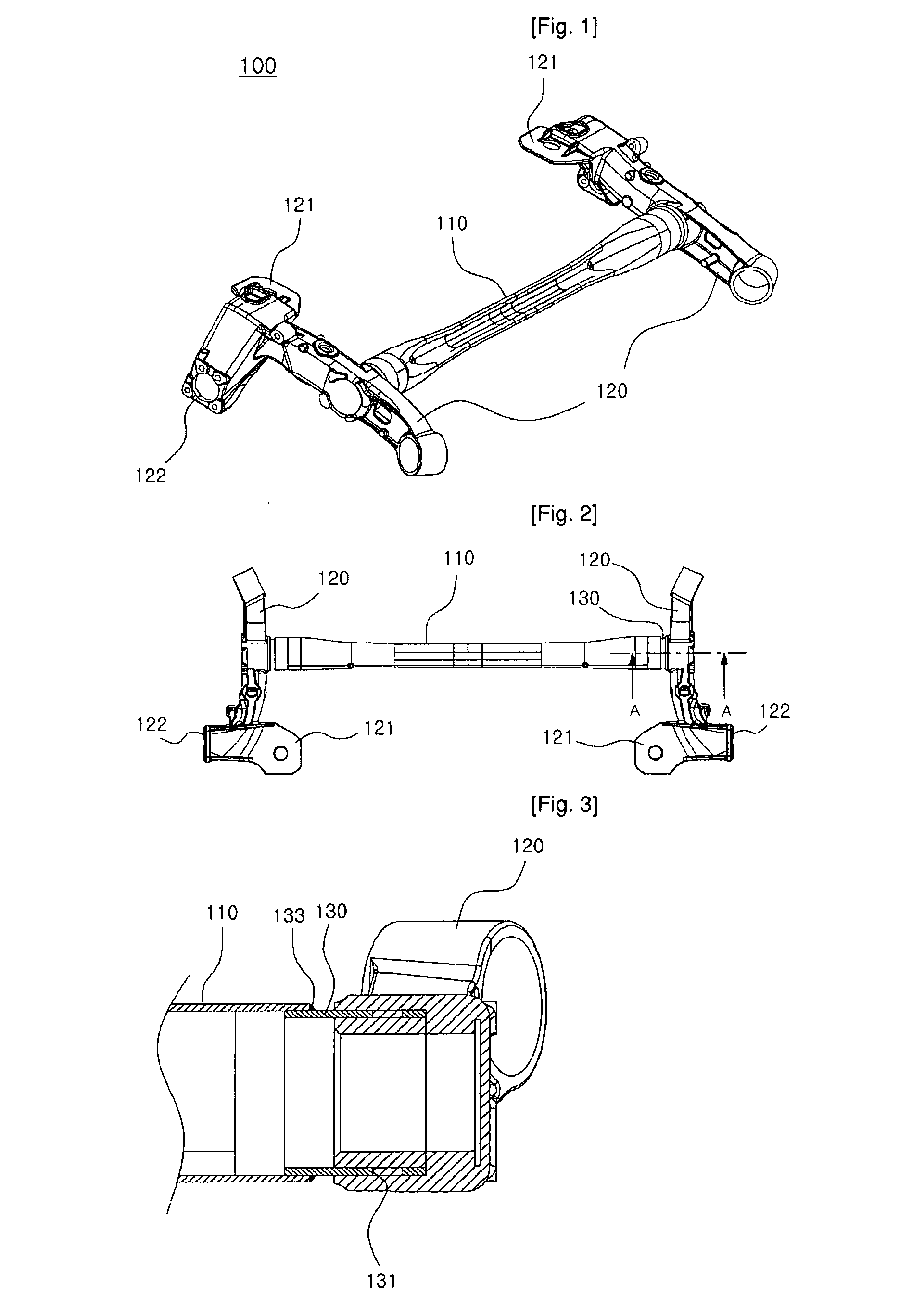
[0023]As shown in FIGS. 1 and 2, a torsion beam axle 100 according to a first embodiment of the present invention includes a torsion beam 110 and a plurality of trailing arms 120 coupled to opposite ends of the torsion beam 110.

[0024]The torsion beam 110 has a continuous tubular shape, in which the cross section of an intermediate portion thereof is curved in a U or V shape, and a cross section of each end thereof is circular. This continuous tubular shape allows the middle of the torsion beam 110 to easily undergo elastic torsion deformation. The torsion beam 110 is typically manufactured by hydro-forming a hollow tube having a circular cross section under a predetermined pressure. The to...


PUM


Abstract

A torsion beam axle includes a torsion beam, a plurality of trailing arms made of a material different from that of the torsion beam, and connecting tubes made of a material better than that of the trailing arms with respect to weldability with the torsion beam, and integrally coupled to the trailing arms at one end part thereof, and welded to the torsion beam at the other end part thereof. Thereby, the coupling force between the trailing arms and the torsion beam made of different materials can be improved.

Description

TECHNICAL FIELD[0001]The present invention relates, in general, to a torsion beam axle, and more particularly, to a torsion beam axle having connecting tubes for reinforcing coupling force between a torsion beam and trailing arms.BACKGROUND ART[0002]As is generally known in the art, a torsion beam axle is a kind of suspension system that connects the wheels to the chassis in a vehicle, and includes a plurality of trailing arms that are coupled to the rear (or front) wheels and the chassis, and a torsion beam that connects the trailing arms.[0003]The torsion beam axle has major technical problems in that it must enable good performance of an independent suspension system by implementing a torsion beam having a concurrent torsion characteristic when torsion occurs between the left-hand wheel and the right-hand wheel and simultaneously secure trunk space and price competitiveness, and in that it must make the chassis light by means of an optimized design of the torsion beam.[0004]In th...

Claims


Application Information

Patent Timeline
Patent Type & Authority Applications(United States)
IPC IPC(8): B60G11/18
CPCB60G21/051B60G2206/20B60G2204/4307B60G2200/21B60G7/00B60G7/02B60G7/04B60G11/18
Inventor KO, JUNG-MIN
Owner AUSTEM CO LTD
Why Eureka
Try Eureka