
Method for manufacturing zirconia slurry for forming porous surface on abutment and crown of ceramic implant and method for manufacturing implant using the same

a technology of ceramic implants and zirconia slurry, which is applied in the field of manufacturing a zirconia slurry for forming porous surfaces on abutments and crowns of ceramic implants and a method for manufacturing implants using the same, can solve the problems of no improvement in durability of veneers and bondings, and no technology having functions applicable to actual teeth of patients, so as to achieve the effect of drastically increasing the coupling force between components

Active Publication Date: 2020-08-27
DMAX
View PDF0 Cites 0 Cited by
  • Summary
  • Abstract
  • Description
  • Claims
  • Application Information

AI Technical Summary

Benefits of technology

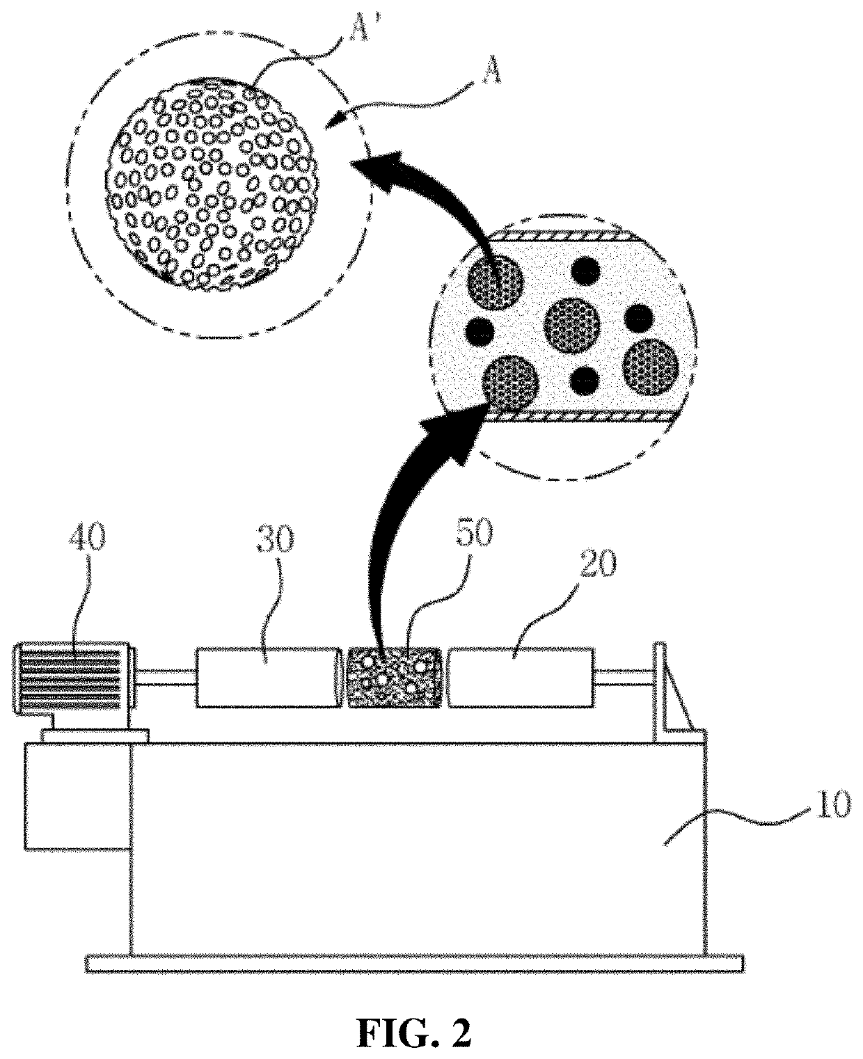
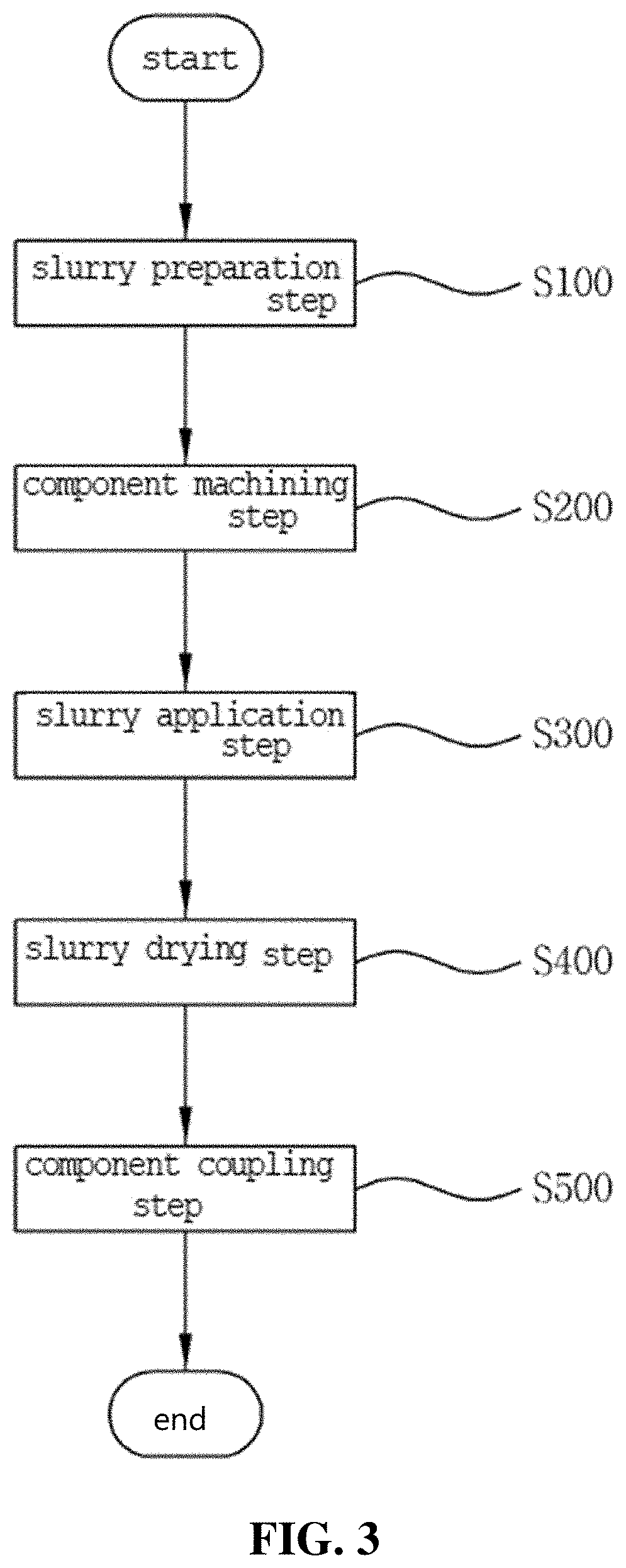
The present invention provides methods for manufacturing a zirconia slurry and an implant using the slurry. The slurry can be applied to the components of the implant to form porous surfaces, increasing the coupling force between the components. Additionally, the slurry can contain nanoparticles, improving the coupling force between the components. The slurry can also have different distribution flows, improving friction areas and coefficients of the components to optimize the coupling force between them.

Problems solved by technology

However, the conventional technology is just a method that is capable of manufacturing the ceramic veneer to a relatively thin thickness, so that there is no improvement in durability of the veneer and a bonding force between the veneer and a surgery tooth.
A variety of methods have been developed to improve a coupling force between the components of the implant, but unfortunately, there is no technology having functions applicable actually to a patient's tooth.

Method used


Image

  • Method for manufacturing zirconia slurry for forming porous surface on abutment and crown of ceramic implant and method for manufacturing implant using the same
  • Method for manufacturing zirconia slurry for forming porous surface on abutment and crown of ceramic implant and method for manufacturing implant using the same
  • Method for manufacturing zirconia slurry for forming porous surface on abutment and crown of ceramic implant and method for manufacturing implant using the same

Examples


first embodiment

[0070]Characteristics of Zirconia Powder According to Zirconia Materials

[0071]So as to check influences of zirconium precursors as starting materials, zirconium acetate, zirconium nitrate, and zirconium chloride were used, and a 3M KOH solution as the precipitation agent was added. Next, the hydrothermal synthesis for the mixture was carried out at a temperature of 200° C. for eight hours.

[0072]Changes in the fine structures of the zirconia powder according to the kinds of the zirconium precursors are indicated by the following graph.

[0073]In the above graph, (a) is zirconium acetate, (b) is zirconium nitrate, and (c) is zirconium chloride. Through the first embodiment, all of the zirconia powder (a), (b) and (c) are synthesized to monoclinic phases, and as appreciated from the graph, if the zirconium chloride is used as the precursor, the XRD peak intensity of the zirconium chloride becomes lower and broader than those of the zirconium acetate and the zirconium nitrate. If the zir...

second embodiment

[0077]Characteristics of Zirconia Powder According to Precipitation Agents

[0078]So as to check the fine structures and crystalline phases of the zirconia powder according to kinds and concentrations of precipitation agents, a reaction temperature was fixed to 200° C., reaction time was fixed to 8 h, and KOH and NaOH as the precipitation agents were used, while their concentrations were being changed to 0.1, 1, 2, and 5M, thereby making respective zirconia powder.

[0079]Changes in the fine structures of the zirconia powder according to the kinds of the precipitation agents are indicated by the following graph.

[0080]In the above graph, (a) is a concentration of 0.1 M of a precipitation agent, (b) is that of 1 M, (c) is that of 2 M, and (d) is that of 5 M. The powder to which the 0.1 M KOH is synthesized has both of tetragonal phases and monoclinic phases, and the powder to which the 1 to 5 M KOH is synthesized has only monoclinic phases. As appreciated from the graph, the higher the c...

third embodiment

[0084]Characteristics of Zirconia Powder According to Reaction Temperatures and Time

[0085]The zirconia powder was made with zirconium chloride as a zirconium precursor through a hydrothermal process, and after 0.1 M KOH was added to the zirconia powder, the zirconia powder was synthesized with reaction temperatures of 100, 150 and 200° C. and reaction time of 4, 8, 12 and 24 h so as to check the fine structures and crystalline phases thereof according to the reaction temperatures and time.

[0086]Changes in the fine structures of the zirconia powder according to reaction temperatures are indicated by the following graph.

[0087]In the above graph, (a) is a temperature of 100° C., (b) is that of 150° C., and (c) is that of 200° C. If the zirconia powder is synthesized at a reaction temperature of 100° C., it has tetragonal phases, and spherical powder particles having sizes of about 10 nm are observed. Contrarily, if the zirconia powder is synthesized at a reaction temperature of 150° C...


PUM

PropertyMeasurementUnit
temperatureaaaaaaaaaa
inner diameteraaaaaaaaaa

Abstract

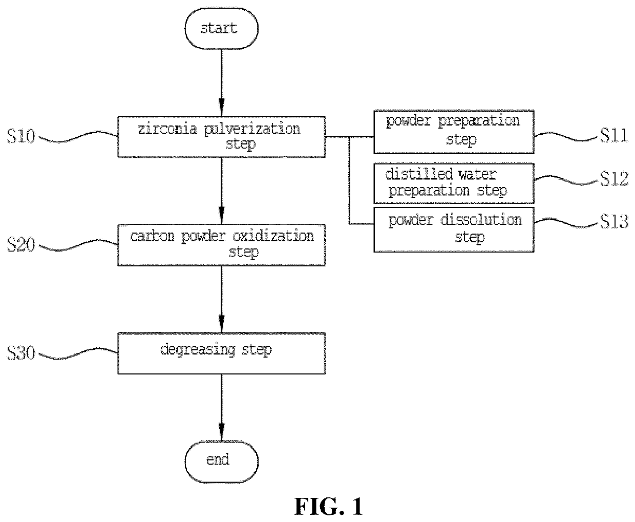
The present invention relates to a method for manufacturing a zirconia slurry for forming porous surfaces on an abutment and a crown of a ceramic implant, the method including: the zirconia pulverization step (step S10) of putting zirconia powder, carbon powder as a foaming agent, and an organic binder in a ball mill and agitating and pulverizing the zirconia, carbon powder, and organic binder to allow the mixed zirconia powder to have nanoparticles; the carbon powder oxidization step (step S20) of heating the zirconia powder mixed with the carbon powder to a temperature of 1200 to 1800° C. and oxidizing the carbon powder to a concentration of 10 to 40 wt % to allow the porous surfaces to be formed on every particle of the zirconia powder; and the degreasing step (step S30) of putting a dispersing agent and a solvent in the zirconia powder whose particles have the porous surfaces to make a zirconia solution and removing the organic binder from the zirconia powder.

Description

CROSS REFERENCE TO RELATED APPLICATION OF THE INVENTION[0001]The present application claims the benefit of Korean Patent Application No. KR10-2019-0020384 filed in the Korean Intellectual Property Office on Feb. 21, 2019, the entire contents of which are incorporated herein by reference.BACKGROUND OF THE INVENTIONField of the Invention[0002]The present invention relates to a method for manufacturing a zirconia slurry for forming porous surfaces on an abutment and a crown of a ceramic implant and a method for manufacturing an implant using the same, and more particularly, to a method for manufacturing a zirconia slurry for forming porous surfaces on an abutment and a crown of a ceramic implant and a method for manufacturing an implant using the same that are capable of manufacturing the zirconia slurry having nanoparticles through a ball mill in more improved way than the existing way, allowing the manufactured zirconia slurry to be applied and dried on specific objects to form the p...

Claims


Application Information

Patent Timeline
Patent Type & Authority Applications(United States)
IPC IPC(8): A61C13/083A61C5/77A61C5/73A61C8/00
CPCA61C5/73A61C8/0012A61C13/083A61C5/77A61C8/0048A61C8/0013A61C5/20A61K6/802C04B41/009C04B2111/00836C04B41/89C04B41/4582C04B41/52C04B35/48C04B41/5042C04B41/48C04B41/5035A61C13/0003A61C13/02A61C2008/0046A61C13/00
Inventor PARK, TAE SEOK
Owner DMAX
Learn More