Magnetostrictive stress sensor
a stress sensor and magnetic field technology, applied in the field of magnetic field, can solve the problem that the conventional magnetic field stress sensor is not sufficient for practical implementation, and achieve the effect of accurate and precise stress detection
- Summary
- Abstract
- Description
- Claims
- Application Information
AI Technical Summary
Benefits of technology
Problems solved by technology
Method used
Image

Examples
first embodiment
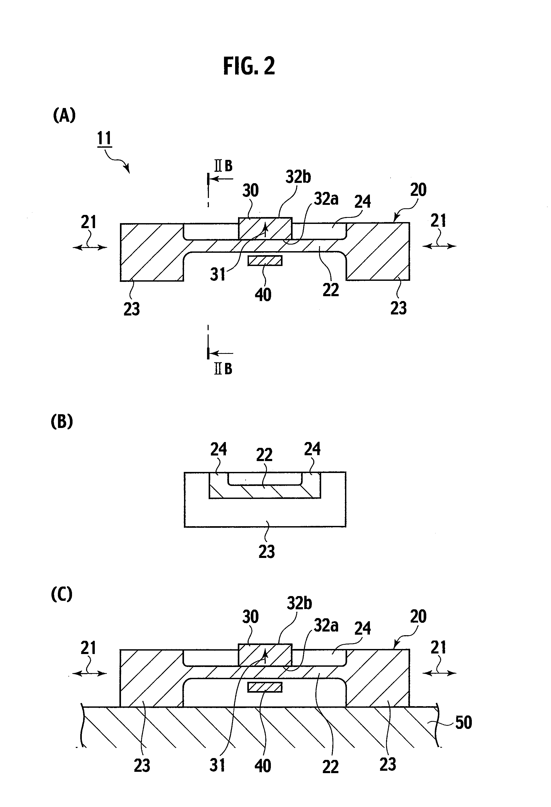
[0045]FIG. 2(A) is a cross sectional view showing a basic structure of a magnetostrictive stress sensor 11 according to a first embodiment of the present invention. FIG. 2(B) is a cross sectional view taken along the line IIB-IIB in FIG. 2(A). FIG. 2(C) is a cross sectional view showing that the magnetostrictive stress sensor 11 in FIG. 2(A) is mounted to a stress-applied member 50 on which the stress acts.
[0046]Referring to FIG. 2(A), the magnetostrictive stress sensor 11 includes a magnetic member 20 having magnetostriction, a permanent magnet 30 disposed close to the magnetic member 20, and a first magnetic sensor 40 for detecting leak magnetic flux on a side opposite to the permanent magnet 30 with respect to the magnetic member 20. The leak magnetic flux changes depending on the stress acting on the magnetic member 20. However, the first magnetic sensor 40 detects the change of the leak magnetic flux, to thereby detect the stress acting on the magnetic member 20. With the magne...
second embodiment
[0081]FIG. 3 is a cross section showing a magnetostrictive stress sensor 12, according to a second embodiment of the present invention. Members common to those according to the first embodiment are denoted by the same numerals or signs and therefore an explanation thereof is to be partly omitted.
[0082]The magnetostrictive stress sensor 12 according to the second embodiment is different from the magnetostrictive stress sensor 11 according to the first embodiment, in that a first yoke 60 is disposed in such a manner as to face the permanent magnet 30.
[0083]The first yoke 60 made from the material same as that of the magnetic member 20 is disposed on the magnetostrictive stress sensor 12, in such a manner as to face the second end face 32b opposite to the first end face 32a facing the magnetic member 20, of the first end face 32a and second end face 32b which are orthogonal to the magnetizing direction (refer to arrow 31). The first yoke 60 is so disposed as to contact the second end f...
third embodiment
[0086]FIG. 4 is a cross section showing a magnetostrictive stress sensor 13, according to a third embodiment of the present invention. Members common to those according to the first and second embodiments are denoted by the same numerals or signs and therefore an explanation thereof is to be partly omitted.
[0087]The magnetostrictive stress sensor 13 according to the third embodiment is different from the magnetostrictive stress sensor 12 according to the second embodiment, in that other than the first magnetic sensor 40, there is provided a second magnetic sensor 45 (otherwise referred to as “another magnetic sensor 45”) for monitoring a magnetic flux of the permanent magnet 30 in a state not depending on the stress acting on the magnetic member 20.
[0088]In addition to the structure of the magnetostrictive stress sensor 12 according to the second embodiment, the magnetostrictive stress sensor 13 has such a structure that the second magnetic sensor 45 is disposed outside the first yo...
PUM
 Abstract
Description
Claims
Application Information
PatSnap Eureka turns technology decisions into work you can execute. Powered by our Innovation Knowledge Graph, it runs expert workflows across engineering, life sciences, materials and intellectual property. Get your review-ready output in minutes.


